2323 TRIODE "JBS-1"
Page updated 2018.
2323 two channel triode amp with 6CM5 first made before 1998
now much improved and
easier and better for anyone to build. This page teaches us how to
learn from our mistakes.
Now in 2018 with 4040 JBS-2, with 6CM5 in
40% UL and with much better OPT.
One of the first tube amps I built was the 2323 JBS-1 which stands
for 23W + 23W Junk Box Special No 1.
Anyone who read the last page in 2006 about this amp's development
may have smiled that so much could
be done with so little. But a few ppl around the world did copy
what I did, using easier to get 12AU7 input
and driver tubes, and with better ( or even worse OPT ), and with
2 x 6CM5, EL36, or PL36.
I have so much new useful information I will not repeat what I
said in 2006 which included a lot of bullshit.
6CM5 was made originally for TV set line output stage to
produce the high Vac to move the electron
beam from one side of screen to other 525 times a second.
There are many data sheets for EL36 aka 6CM5 both with 6.3V x 1.2A
( or PL36 which has heater
25Vac x 0.3A. ) The best data sheet which even includes triode
data is at :-
EL36-Telefunken-in-German.pdf
The triode properties of 6CM5 used here are :-
Ea = +375V,
Eg2 = +375V,
Idle Ia = 50mAdc,
Pda+g2 at idle = 19W,
Anode Ra at idle point = 750r,
Triode g1 µ = 5.5,
Triode gm = 0.073mA.V,
Screen g1 gm = 1.23mA/V.
Anode tetrode Ra = 10k approx.
Anode gm = 0.1mA/V approx.
Anode Ra at 0.0mA to 100mA = 550r.
Class A triode RLa load = 6k4, anode Po = 7.8W.
Class A triode gain = 4.9.
Class A PP triode load for two tubes = 12k8, anode Po = 15.6W.
There are a number of 6CM5 for sale in Australia where they were
used in thousands of TV
sets before solid state finally became reliable for vertical
deflection purposes in late 1970s.
Melody amps used EL36, same as 6CM5. In 2018 I saw an add on Ebay
with many EL36 in
large box, and labelled Melody, so maybe made in China or of
dubious origin.
Beware those selling used EL36 or 6CM5, and they may not be NOS,
but "used in box" which
means they may have been removed from a Melody amp, replaced with
new ones, and amp
owner would have paid dearly, and now the service guy wants to
sell all these "pulls" which
may or may not work OK.
In 1990s, there were plenty of NOS 6CM5 for replacements in TV
sets and in stocks of older
techs who were still repairing old TV sets right up until they
retired.
Most of those stocks have now gone, or are stacked in a basement,
attic, or under a bed,
forgotten in a closet, and their present owner would never read
silly website pages like this one.
Therefore, if you make an amp for 6CM5, be sensible, make sure it
can also use 6L6GC, KT66, EL34,
KT88 or 6550.
This means the PSU must have PT with VA rating above 300VA and
be able to provide
6.3Vac x 10A for heater filaments and B+ with 300V-0-300V HT
winding good for
400Vdc x 300mAdc.
Everyone worries about 6CM5 or EL36 idle Pda but it seems max Pda
= 17.5W and max Pdg2 = 3.5W
so total max Pda+g2 = 21W. I found the anode did not glow dull red
until Pda = 28W.
The idle condition for triode was OK with Ea = Eg2 = 375V with
Ia+Ig2 = 50mAdc, so Pda+g2 =18.75W.
Another tube that is very similar to EL36 / 6CM5 is GE 6FW5, see
data at
6FW5-like-6CM5-EL36.pdf
The 6FW5 is not a common tube and a brief look at Google showed
none for sale. You should always
purchase 12 of these or none at all, so that you have one full
replacement quad plus spares.
6CM5 / EL36 / PL36 HAVE ANODE TOP CAP CONNECTIONS AT +375V DC
POTENTIAL.
Always use well insulated anode wire + top cap insulator and / or
perforated steel cover over all tubes
with maximum hole size 5mm.
YOU HAVE BEEN WARNED!!!!!!!!!!!
In February 2018, I still owned the original JBS-1, with its 12W
"medium-fi" PP OPT meant for 12W
max from a pair of 6GW8 or EL84.
A couple of ppl in the world have wanted to build the JBS-1, and
when I carefully examined the original,
I realized I just could not let anyone build the original because
the amp and PSU schematics have a couple
of design faults which needed to be changed.
Fig 1. Original JBS-1 amp, 1 channel :-
The note about NOT building this has been added in 2018.
The information is same as drawn in 2006 but there are many things
not explained, or just not right
so please ignore this schematic.
When I very carefully examined the old amp, there were some minor
differences to what was in the
amp and in this schematic. The 23W was absolute max possible Po in
triode AB1 with a load = 2r0.
The best load for best music was 8r0, where about 12W+ was
maximum.
Despite its low power, the consensus amoung ppl who borrowed JBS-1
was that it sounded better
than their budget 40W SS amps, and that the 6CM5 did better than a
pair of EL84 in UL mode, and
I compared it to an original Quad-II amp and JBS-1 was better.
But during sine wave testing, if I pushed one channel of the two
to make 20W, the B+ sagged from
+375V to +350V, so something was not too good about the power
supply. It was happiest making
12W, and with much of the initial Po in class A.
So in March I spent a few days to make the JBS-1 a lot better.
Fig 2. March 2018 version of JBS-1.
This gives a much more detailed and accurate idea of what is
really possible with 2 x 6CM5, using
old 1960 OPTs meant for 12W.
Fig 3. Original PSU for 2323 JBS-1.
This PSU has a number of terrible design problems.
1. The C values used for B+ should be higher.
2. The two transistors MJE340 and BU208A are Darlington connected
and attempt to work
as a capacitance multiplier, something favoured by 1960
accountants who also did the design work.
100Hz ripple is much reduced at C8 by R2+C6+R5+C8, in theory. I
found I'd replaced C8 by 4u7.
The theoretical 100Hz attenuation factor is more than 1/ 10,000.
But in fact, there is not that much.
There is 13Vac at 100Hz at top C2+C3, and although Rc of the bjts
is high, there is some 100Hz Iac
in base currents. The output resistance of the arrangement is
quite poor because if Idc to tubes increases
the Ic : Ib hfe ratio is high for the Darlington pair, so you get
high Vdc increase in R2+R5 so base Vdc
goes low, and emitter Vdc follows it. Rout after R8 is effectively
higher, ie worse that if I had used a
crummy 1960 PT with high Rw and a tube rectifier. It was time to
retire this dreadful experiment.
I did not want to convert it to a B+ regulator. Not shown on
schematic are 5 taps on HT winding
for 134Vac to 170Vac, and I figured I could replace Horrid
Transistors with a choke, and use a tap
for 150Vac.
3. There are several bias -Vdc needed around the amp circuit. The
output tube B+ is 375Vdc approx
so that for best operation of V3+V4 in LTP, the B+ for the stage
needs to be high because the 6CM5
in triode mode has low µ of about 5.5 so that gain is low, and max
Vg1 is over 60Vpk allowing for
some charge build up in coupling caps. I measured about 48Vrms
max.
There must be a negative supply rail to give -60Vdc bias for g1 of
6CM5, so g1 of V3+4 could easily
be at a -Vdc to make their effective B+ higher than +350V. The CCS
for LPT can have its emitter
resistor taken to a low -Vdc, with base Vdc between the lowest
-Vdc rail and the g1 -Vdc of V3+4.
The 44Vac winding makes -117V with doubler rectifier and this is
filtered by R3-C7-R6-C9.
I chose to shunt regulate the -Vdc with what appears to be 3 x
24Vzd, each 5W.
The regulated -72Vdc is applied to the 4 pots for adjusting the
fixed bias -Vdc for the 4 x 6CM5
grids.
The trouble with this arrangement is that mains Vac can and does
change here between 235Vrms
and 255Vrms. If the bias is set on a day where mains = 240Vrms,
then the increase of mains to
255Vrms causes B+ to rise from 375V to 398Vdc, and the Ra of 6CM5
= 750r with fixed Vdc
between g1 and k. Thus B+ rise of +23V causes Iadc increase of
30mAdc, and Pda increases to
398Vdc x 80mAdc = 31.8W, and 6CM5 would overheat badly and self
destruct with excessive
heat before any mains fuse blew.
Therefore the grid bias -Vdc MUST NOT BE REGULATED, and
must be allowed increase like the
anode +Vdc, and calculations revealed to me that it makes sense to
have a larger % change for bias
-Vdc than the change of B+ due to mains Vac changes. Such changes
of mains Vac make the B+
change slowly, and the R+C behaviour allows all this to happen
without risk of LF oscillations.
The changes to bias -Vdc to g1 of V3+4 and for Vbe for CCS MJE340
allows slight change to
V4+V4 operation, but nothing that makes operation worse in any
way.
Fig 4. Revised PSU for 2323 JBS-1 amp.
This PSU includes some improvements to original which I did in
March 2018.
When I first built the 2323, over 20 years ago, I tried a Ferguson
PT but even with no load it got
hot, so I stripped it down to get the T38mm x S40mm core. I had
some other E+I of same size,
so I added 22mm to stack to get T38mm x S62, so the core became
rated for over 200VA.
I rewound the bobbin with Bac = 0.8T, and the result with this old
iron is excellent, with temperature
rise < 15C, and good natural regulation of B+. So the old PT
has been retained.
B+ supply has much larger C values of 3 x 470uF and has a choke
instead of the solid state
"capacitance multiplier". The 100Hz at top C3a = 2.3Vrms, and at
top C4 is is less than 2mV.
R1 needed careful trial of R value to get +375Vdc at 4 x 6CM5
anodes when each 6CM5 has
Ikdc = 48mAdc.
With heavy class AB operation, B+ sags from +380Vdc at OPT CT to
about 360Vdc with sine wave
signal at clipping to low value RLa-a. Rout of B+ supply is less
than 200r.
The B+ at OPT CT = +380V, each half primary of OPT has Rw = 83r,
so 50mAdc causes drop
= 4.1Vdc, so anode B+ is close to = +375Vdc. The B+ for V3+V4 =
+364V, and for V1+V2 it is
+300Vdc.
The B- rail -Vdc uses 2 x 1,000uF in doubler, but has 2 x 820uF
for C9+C10, and 100Hz hum is
extremely low at -100Vdc output at bottom of C10. The total Idc is
about 27mAdc, and -100Vdc
is possible instead of -73Vdc, and this allows more negative
-64Vdc to bias V3+4 grids so the
two tubes can have higher B+ to Ek = 360Vdc + 55Vdc = 415Vdc which
allows high RLa and
leads to lowest possible THD for driver stage.
The "on" LED has been changed to green, and works from the -Vdc
supply. If the green LED
does not come on after switching on, there is no -Vdc bias and if
the owner is alert, he will turn
off the amp. If he he does not turn off the amp the output tubes
will try to each conduct about
0.5A at 15 seconds after turn on and the 0.5A fuses in series with
B+ and each OPT will blow
if the mains fuse does not.
Instead of 3 zener diodes in series, there is R8, R9, R10 and C11
47uF keeps the -64Vdc for
V3+4 grids quiet, and fairly constant. C12 keeps the 14Vdc quiet
between MJE34 bases and
bottom of emitter R 1k8 which sets the current value for CCS. The
13.3Vdc remains stable across
1k8 on amp schematic so CCS is normally 7.4mAdc at each channel,
with each 1/2 of 6CG7
having 3.7mAdc. If mains varies, the CCS current varies slightly
but not enough to much alter
the Ea or Iadc for V3+4.
-100Vdc feeds the 33V zener diode in series with 4 parallel 10k
trim pots plus 12k0 to 0V.
This allows bias to be set fairly easily between -56Vdc and
-66Vdc. If mains changes from
240Vac to 252Vac, +5%, the B+ rises from +380Vdc to 399Vdc, which
would cause tubes to
overheat if bias -Vdc was regulated.
If B+ increases +5%, the B- 100V also moves 5% to -105Vdc. This -5
Vdc change is applied to
bottom of bias pots which move from -66Vdc to -71Vdc, and the
average grid -Vdc bias of -61Vdc
moves to about -65.6Vdc, and bias change = about 7.5% of normal
Bias -Vdc.
A +19Vdc increase for each 6CM5 with fixed bias will cause Iadc to
increase +25mAdc, and
increase idle Pda to 394V x 75mA = 30W, and tubes become much too
hot. The reason is that
6CM5 has Ra at idle point = 750r, because screen has gm = 1.2mA/V
approx.
The grid bias -Vdc change of -4.5V reduces Iadc by about 30mAdc
because grid gm is about
7mA/V.
Therefore the Pda with 5% mains increase will be about 394V x 45mA
= 17.7W, so tubes remain
cool.
If mains Vac reduces from 240Vac to 230Vac, something I have not
seen yet, -4.2%, B+ change
= -16Vdc, Ia reduces -21mAdc. The bias change = +5.8% for Eg1
change = +3.5Vdc, increase of
Ia = +20mAdc, Pda = 359V x 49mA = 17.6W.
The original JBS-1 had 20k bias adjust pots which may have even
been log types.
There was 23Vdc across the pot, so the slightest turn of pot shaft
gave large Idc change.
The amp needed to be removed from the audio gear bench, turned
upside down on carpet floor,
bottom cover removed, and each bias pot adjusted with a DMM
clipped across each cathode
Rk of 10r0.
For the very many amp owners who love tubes, but who are clumsy
and liable to make horrible
mistakes while trying to set the bias, this operation could easily
cause the owner to get a bad
electric shock or damage the amp without knowing he has.
I put 4 x 25mm dia x 10k linear trim pots placed in a side panel
of amp chassis with 4 recessed
test points for each Rk above each pot screw. Test point is small
brass plated philips head c/s
screw in a block of wood inside the amp panel with c/s 10mm dia
access holes. It is now easier
and more reliable to check bias, and to set it without moving the
amp off its bench. All that is
needed is a cheap DMM set to 0-2Vdc range and with red probes held
against test point, and
black against the chassis, the nearest pot screw can be turned
with a thumb nail ( or a small
screw driver ) so that +0.48Vdc appears on meter. It is done for
all 4 test points 20 seconds after
turn on and repeated at 40 seconds and at 1 minute and then 5
minutes and again later if you want.
The initial +0.48Vdc may increase as the tubes warm right up, and
then need to be adjusted down.
Once the bias is set for the fully warmed up level, there should
be no need to repeat the biasing
procedure for months, or even years. But with new tubes or any
replacements, it is necessary
to check bias and to have a DMM kept handy.
The original JBS-1 had only Iac heating for all tubes, and I saw
no reason to change this, and there
was not much room under chassis for yet more high C values and
diodes for Idc heating to the two
V1+V2 at each channel. The PT has 2 heater windings each 6.3Vac
with CT taken to 0V. Both
windings are parallel.
There was no original protection circuit board used on original
amp, and I was lucky that a 6CM5
did not have bias failure. But remarkably, the bias was about
right after 20 years.
For a fixed bias amp, keep a cheap DMM handy, and check bias
weekly if you are obsessive.
I know some of you will make this amp. Therefore I need to include
a bare minimum protection
schematic, see Fig 7 below which has a full minimum protection
schematic.
For those wanting to built this amp, they will never find any
commercially made PT for a doubler
rectifier. Voltage doublers became possible when Si diodes with
high peak inverse voltage rating
and current rating of amps became available in 1960s. Tube amp
makers quickly changed to
Si diodes because they were more reliable than tubes, had peak
current rating 15 times higher than
1/2 a GZ34, OK for 200mApk charge current, and to 47uF max. The Si
diode has on resistance of
1r0, unlike 1/2 GZ34 with Ra 30r, so Si diodes allowed HT windings
with low winding resistance
and peak charge current of 3A or more into 470uF. Therefore B+
rails built with Si diodes, low Rw,
high C values gives natural regulation almost as good as a
regulated + using tubes, which itself
can be terribly unreliable, power consuming, costly to build and
maintain. The CLC type of filter
with Si diodes gave better regulation than using LC "choke input"
filter.
For a 2323, or 4040 below, most ppl will try to buy a PT already
made, and most have the old
fashioned centre tapped HT winding which was suitable for a GZ34
tube rectifier, or a pair of them,
with each having its 2 diodes in parallel.
Fig 5. Alternative HT windings.
Few people ever use a voltage doubler type of rectifier. But
they work extremely well with Si diodes
and the doubler HT winding has 1/2 the turns for a bridge
winding, and 1/4 of the turns needed for
a CT winding.
But few companies make PTs with single HT windings for the 4
diodes of a bridge, and most tube amp
PT have a CT winding usually to suit a single GZ34, or have two
GZ34 with both its diodes parallel.
Hammond make a range of tube PT, I suggest you visit
http://www.hammondmfg.com/300series.htm
and for 2323 I suggest this one :-
http://www.hammondmfg.com/pdf/EDB372JX.pdf
This is rated at 243VA.
243VA input includes 9.4W heat in RwP = 9.4r.
HT winding = 300V-0-300V at 288mA = 172W, including 9.6W heat in
RwHT = 116r.
5V heater at 4A, = 20W, including 1W heat in RwH = 0.064r.
6.3V x 8A = 50W, including 3.5W heat in RwH = 0.054r.
Bias generation needs negligible power.
If you have two 1N5408 Si diodes, it makes about
+408Vdc with load of 240mAdc. But the data shows the HT is
320V-0-320V with no load and 120V input with
both primaries paralleled. With 240Vac input with both Pri in
series, the same non loaded
Vac will appear. 240V Pri has RwP = 9.4r,and HT has RwHT = 116r,
or 58r for each 1/2 HT.
S = 584with mary 9V a t sec
DO NOT use a tube rectifier.
There is a 50V tap which can power a doubler for -130Vdc which
is RCRC filtered to get -100Vdc to feed
the grid bias network and to supply Idc for V3+4 CCS of both
channels.
The 372JX has heater windings for 6.3V x 8A and 5V x 4A. The 5V
winding is useless and need not be used,
unless as a doubler to make about 10Vdc to power CRC for 1.2Adc
for 2 x 6CG7 for V1+2.
The 6.3V is OK for all tubes which operate with 6.3V heaters. 4
x 6CM5 and 4 x 6CG7 require 6.3V x 7.2A.
None of the Hammond PT have a 25V x 0.3A winding for PL36, and
you will need a small 60VA transformer
with 240V : 25V.
The simplest B+ rail has the two HT 1/2 windings with 1N5408 a
470uF cap to get +400Vdc at 0.25Adc and
100Hz Vac = 1.2Vrms. Using RC filter, R = 56r, 10W, and second C
= 470uF, 100Hz Vac = 0.07Vrms, low
enough.
For better B+ filtering use a Hammond choke, 193L which is 2.6H
for 300mAdc, Rw = 57r, and 100Hz
ripple will be < 0.003Vrms. See choke catalogue at http://www.hammondmfg.com/153.htm
When I tested my reformed amp and PSU, I got the following power
with the old Ferguson OPT with ZR 1,156 :-
18k5 : 16r0 10.6W, all pure class A, Rw loss < 5%,
13k9 : 12r0 12.8W mainly class A,
9k3 : 8r0 16.5W AB, Rw loss 12%
6k9 : 6r0 19.1W AB,
4k6 : 4r0 21.6W AB, Rw loss 24%
3k5 : 3r0 23.5W AB,
2k3 : 2r0 23.8W AB, Rw loss 40%+.
Therefore if there is 23.8W for 2r0, the anode power must be
33W, and total Rw + anode load = 3k3, approx.
The idle Pda of 2 x 6CM5 = 2 x 19W = 38W, and maximum pure class
A triode efficiency is about 33% so
you should get about 12.7W of pure class A max. This is very
close to the performance of 2 x KT66 in 1947
Williamson triode amp. With the OPT I have used here, the Rw
loss % is high but only where speakers
are less than 8r0, and in fact the losses here are no worse than
for a Quad-II amp OPT.
Better OPT would be from Hammond, see 2 better OPT such as
1650HA see
http://www.hammondmfg.com/pdf/EDB1650HA.pdf
This is a 40W OPT for 6k6 : 4r0, 8r0, 16r0.
Fig 6. 40W UL amp schematic for one channel 2018.
This is very much like the above Fig 2 for 23W triode amp.
But the original 23 triode amp used 12W Ferguson OPT with core
T25mm x S44mm, 3P x 2S
interleaving, RwP 232r, RwS 0.5r, 17% UL taps which don't give
enough screen FB.
Ferguson OPT saturated at 35Hz at only 16W.
In Fig 6 I have used OP21, something I found in my stocks with
core T32mm x S44mm, 4P x 3S
interleaving, RwP = 116r, RwS = 0.21r, 40% UL taps which were
found to work very well with 6CM5.
and half the winding Rw.
OP21was able to 40W with Fsat = 20Hz.
Fig 6 shows best practice I can think of for a 40% UL amp :-
1. The amp is fully integrated, with 6 x RCA sockets for 5
selectable audio sources plus one RCA for
recording, for each channel, which means having RCA cables to a
sound card on a PC or whatever is
needed for digital recording because in 2018, nobody is making a
cassette recording for music in the car.
But having a choice of 5 inputs is still useful.
In my 2323 which is now become a 4040 amp, I do not have this
switched input feature because there
is not enough room on chassis.
Instead, I have single RCA input socket for each channel where
Record RCA socket is shown.
2. The Iadc in all the V1 to V4 triodes is much increased to
have these triodes work at more linear
region, and have better F response.
3. Each channel works with PSU in Fig 4 with a B- rail at -100V
for -85.7Vdc to MJE34 bases, and
-64Vdc to bias V3+4 grids.
4. The V1 line level preamp with source select and volume
control may all be deleted if an owner prefers
to use an external preamp. In this case, 3k9 grid stopper is
used in series with V2g1, R8 1M0 is replaced
with 68k, and 0.33uF is used between R8 and a single RCA input
socket.
5. Notice 2 x 1N4007 diodes in series between each anode and 0V.
This prevents the Va-a going real high
if no load is connected. Without the diodes, where Ia cuts off
in one tube, stored energy in leakage
inductance allows Vac to go to maybe +1,500Vpk. The other anode
moves to -1,125Vpk. The diodes
conduct where anodes reach -1.4Vpk, and the Va at each anode is
thus clamped at +/- 376.4Vpk.
Thus the OPT insulation is not challenged, and arcing at socket
is unlikely.
6. I say that you can put 4,700uFcaps ( 16V rated ) to bypass
the small R23 + R24 10r0.
Although these 10r0 have low R value, with low loads and where
Ia pk can be +0.5A, the Vk pk = +5V,
and that adds to the Vg needed. There is no benefit in any local
current NFB.
4,700uF has XC = 1r7 at 20Hz, so the current FB is very low for
the audio band.
7. Active protection against bias failure of one or more output
tubes.
Fig 7. Minimum active protection schematic.
How this works is explained in schematic. The use of 15r0
current sensing Rk at each cathode
and bypassed with 4,700uF will prevent SCR being tripped by loud
music signals, but use of
sine wave signal can make the average Vdc at cathode rise to
+1.34Vdc where average Idc
reaches about 90mAdc, and class AB peak Ia = about 280mA for Po
= 40W.
Music signals may have occasional clipping at 40W, but average
Po is much lower,
and so music will not cause SCR to latch on and turn off HT
winding.
But where there is a shorted speaker lead, the average anode /
cathode current can be 400mA
at low volume music levels and the HT is turned off.
With a very low speaker load and high volume, the amp will turn
off its HT.
Once turned off, the owner will wonder why the green LED has
gone out and red has turned on.
If he finds the shorted speaker cables, and fixes the problem,
all is well.
He can turn off mains switch, wait a few seconds, and turn amp
on again and if the same thing
happens without any signal, he has a tube problem.
The protection usually only works when one or more output tubes
conducts too much Idc without
any signal.
This happens most commonly when output tubes have reached the
end of their life, and they
begin to conduct too much Iadc, and adjusting the bias makes
little difference to stop the problem.
The protection circuit is highly desirable to stop pyrotechnic
displays of smoke and fire in the
listening room.
In many other amps, I have used a 5VA auxiliary mains
transformer with 240Vac : 12Vac. This is
always on when amp is turned on at its switch and it powers the
protection circuit which has SCR
to open the large PT mains primary winding. This means the amp
is turned off completely if a tube
becomes faulty etc.
It is more work to install this better arrangement, but I ran
out of room for this in my 2323.
How the whole amp works :-
I show the same original V1 1/2 6CG7 for line level preamp which
has unbypassed R6+R7,
so V1 gain = about 4.7. The preamp max Va is about 60Vrms at 2%
THD. CD player maximum
Vo = 1.4Vrms. Balance input network reduces this to 0.96Vrms at
grid, and 4.5Vrms is at anode so THD
is 0.15%, but then at average CD levels of 0.3Vrms, THD of V1 =
0.032%, and not a worry.
V2 is 1/2 6CG7 for power amp input tube which is in differential
mode where the tube amplifies the Vac
difference between input from volume control and the Vac at
cathode which is derived from R18 1k0
and R11 100r divider for GNFB. V2 triode gain is about 16.8.
V3+V4 are two 1/2 of 6CG7 and operating in differential mode
which produce two equal amplitude Vac
at each anode with opposite phase, so V3+4 is a "phase splitter"
but one with differential gain = 15.1.
Alternative input tubes.
6CG7 may be difficult to source if you want NOS. The Russians
have been making 6CG7 since about 2003.
6SN7 can be used as direct replacement for 6CG7, but it is an
octal tube.
6FQ7 is exactly equal. There were 7FQ7 and 8FQ7 and 12FQ7 also
made in large numbers for TV sets
and they were equal except for 7V, 8.4V and 12.6V heaters.
12AU7 big plate type are excellent tubes, but have µ = 17, less
than the µ = 20 for 6CG7, so gain
of V2 and V3+4 will be less, so GNFB R divider must be changed.
12AU7 needs 6.3V x 0.3A
applied to pins 4+5 and 9, or can have 12.6V x 0.15A applied
from pin 4 to 5, The Ra is similar for 6CG7,
6FQ7, and 12AU7.
ANY change of tube type means many other things need to be
changed such as cathode bias networks
of V1 and V2.
12BH7 is an ideal tube for V3+4 , and 6DJ8 could be used for
V1+2.
For 40Vrms at each anode of V3+4 and with opposite phase, the
Va-a between the two anodes = 80Vrms.
The Vg-g between the two grids = 80V / 15.1 = 5.3Vrms.
To enable this function to automatically occur with equal
amplitude Va, low THD, and equal load RLa
for both triodes, V3+4 cathodes both connect to a constant
current sink, CCS, formed by Q1 MJE340
arranged so that its collector input resistance is well over
1M5. Providing the RLa for both anodes are
equal ohms, expect both Va are equal, within 0.5% which is quite
good enough.
The MJE340 is a passive slave to the tubes, and acts like a
passive R = 1M5 and terminated at
-15,000Vdc which is an impractical arrangement. In the past, a
pentode may have been used but the
MJE340 is much easier, and more reliable.
Where you have a CCS the operation allows either two balanced
grid inputs to V3+4, or you can have
one input to V3 grid with the other grid held at 0Vac with large
value C to 0V.
Both V3+4 grids are biased with -64Vdc and the cathodes are at
about -55Vdc, so the the B+
for the two tubes = B+supply +360Vdc plus 55Vdc = +415Vdc. With
Ia = 3.7mA in each triode the
Vdc across 56k dc RL = 207Vdc, so Ea-k = 208Vdc, and this all
allows Va max of about 75Vrms,
and THD is low at 40Vrms for clipping.
V5+6 are the two 6CM5 output tubes with their screen g2 taken to
40% UL taps. Between each g2
and OPT, there is a 470r stopper R to prevent RF oscillation.
Each cathode has a 10r0 series R which is a current sensing R
for setting bias currents by reading Vdc
at 4 test points for the 4 cathodes which should be 0.5Vdc, or
slightly less. 0.5Vdc across 10r0 =
50mA, and it is Ia + Ig2 which equals Ikdc.
The 6CM5 require about -61Vdc where Ea = Eg2 = +375Vdc which is
what I think is maximum
Ea for triode or UL operation. If Ea and Eg2 are both higher,
the grid Eg1 -Vdc must be made more
negative and where Eg1 exceeds -65Vdc, the operation becomes
unreliable and Iadc may not be able
to be controlled, with disastrous results.
The arrangement shown is for "fixed bias" where the bias Eg1 is
adjusted to get wanted Iadc and it
remains fixed after adjustment. Tubes age, and Ikdc can vary for
the same applied Eg1 bias.
Therefore the bias needs to be measured and adjusted each 500
hours, or say every 3 months.
To adjust bias correctly with 4 new tubes :-
You need a cheap DMM, so after buying one, read the
instructions.
A small flat blade screw driver is handy to adjust 4 pot screws,
one for each output tube.
Volume is set at minimum.
The original 2323 now has 4 test points on side of chassis with
4 adjust screws under the test points.
Speakers may be left connected for bias adjustments.
Set all adjust screws at their middle position.
Turn on amp. Turn off mobile phone, get the kids out of the
room.
Measure the mains Vdc at wall socket. If it is 240Vac, then all
is well but if it is 250Vdc, you need to
remember this during bias adjustment.
Right after turn measure Vdc on 0.0 to 2Vdc range between each
test point and chassis metal.
The Vdc = 0.0Vdc right after turn on but after about 10 seconds
Vdc will rise. Measure each Vdc
one after the other, and after 20 seconds, you may have Vdc
between 0.4Vdc and 0.8Vdc.
Where Vdc > 0.6Vdc, turn screw below test point anti
clockwise which should lower Vdc to below 0.6Vdc.
Do this will all 4 test points, and then as tubes warm up, the
Vdc will rise from below 0.6Vdc to above, so
re-adjust all to about 0.65Vdc, and wait for tubes to warm up
more. After 10 minutes, tubes will be near
their normal temperature so adjust all 4 test points to be say
0.7Vdc. Measure all test points again after
1/2 an hour, and all should be between 0.7Vdc and 0.75Vdc.
Now if your mains Vac is high at 250Vac, or +4% above 240Vac,
then adjust Vdc at test points for 4%
less than 0.7Vdc = 0.67Vdc, so all test points should be between
0.65Vdc and 0.67Vdc.
After setting the bias, if the mains Vac rises, applied Eg1
becomes more negative to lessen Iadc so
that tubes don't overheat. If the mains Vac reduces, the applied
Eg1 becomes more positive, increasing
Iadc so tubes do not run to cold.
And all this is probably totally confusing for many non
technical ppl with no skills with tools except to either
wreck a good amp, or injure themselves. Unfortunately, some ppl
get confused and I do not supply pills to
increase IQ bias of amp owners.
This initial bias setting should now be set for months, but
check bias again each week for a month,
and if Vdc of any test point goes higher than +1.0Vdc, and you
cannot turn the screw enough to make
Vdc go lower, you have a bad tube, and it MUST be replaced.
The minimal simple fault protection circuit in PSU schematic
will turn off B+ supply if Ikdc goes above
about 90mAdc. The B+ turns off if you adjust bias Vdc too high
by mistake.
If that happens, turn the bias pot to get lower Vdc at test
point, turn the amp off, wait 4 seconds, then turn
back on and I do hope you get it right this time.
The amp takes advantage of the good triode characteristics of
the 6CM5 or EL36 or PL36 to make good
quality PP triode class AB1 amp for up to 27W per channel, or
40W with UL taps.
Note the R+C Zobel networks used to stabilize the amp even with
only 12dB NFB in the triode amp and
15dB in UL amp.
Amplifier stability.
In Fig 2 above, the 2323
triode amp had R+C zobel to reduce V2 gain at HF. Two zobel R+C
are across
each 1/2 primary, and there is a zobel R+C across OPT Sec.
In Fig 6 above, the 4040 UL amp with much better OPT had no need
for zobel R+C across OPT primary,
and the values for output zobel at Sec and for V2 gain allow for
poles for HF being higher for the better OPT.
With 4040, the maximum NFB is where open loop gain is highest
where no load is connected and in this case
max GNFB with no load = 22dB, and the R+C networks stop all LF
and HF oscillation regardless of what C
load is used. With 8r0 at 8r0 outlet the GNFB = 15dB and Rout
< 0.75r so that damping factor > 10.
The amount of GNFB in dB = 20 x log [ A / ( 1 + { ß x A } ) ]
where
gain A = ( Vo at RL ) / ( Vg-k of input tube ), ß is the
fraction of Vo that is fed back to appear at input tube
cathode. The higher A becomes, the higher the amount of NFB and
the wider the effective bandwidth
but for a flat response the phase shift must be zero, which is
impossible.
"Stability" refers to the how the amp behaves during production
of audio power and whether the amp can
oscillate or not.
Many amps with GNFB will oscillate at LF or at HF without
measures taken to ensure oscillations cannot
occur.
All amps without any GNFB will produce increasing phase shift
below 50Hz and above 10kHz.
The maximum possible phase shift for a typical tube amp will
exceed 180 degrees of phase advance at LF
and phase lag above 10kHz, and if the GNFB R divider network is
connected the amp will always oscillate
where gain without NFB exceeds 1.0, and phase shift exceeds 180
degrees.
To prevent oscillation where GNFB is applied, the gain without
NFB is reduced at frequencies outside
the audio band of 20Hz to 20kHz where maximum GNFB is not
needed, and certainly not wanted.
To understand more, see my page basic-tube-3.html
There are graphs of tube amp F response with and without NFB,
see Fig 6 at bottom of this page.
Fig 6 above for 40W amp shows C6 47n + R12 1M0 and R13 180k
which give -3dB at 19Hz, then
response reduces -16dB to being level at until ultimate pole for
C3 0.47 + R12+R13 1,180k = 0.29Hz.
This R+C network stops most tube amps oscillating at LF where
the OPT primary inductance is low.
Fig 6 above for 40W amp shows C7 1n5 + R14 3k3 which causes -3dB
HF pole for V2 at about where
reactance 1n5 = Ro of V2 10k0, at about 11kHz and response
reduces at -6dB / octave until reactance
1n5 = 3k3 at 32kHz where response level then becomes flat but at
-12dB approx, and phase shift above
32kHz is reduced and the ultimate HF pole is moved to higher F.
At above 20kHz, many speakers have rising impedance, Z, so the
OPT has no R load above 20kHz.
In addition, the OPT leakage inductance LL and primary shunt C
between anodes forms a second order
LPF which causes 90dB phase lag at the filter's -3dB point, and
this may help cause HF oscillations so
in Fig 2 above for 23W triode amp I have 2n2 + 1k5 across each
1/2 primary to reduce HF gain of the
output tubes above 40kHz.
In Fig 6 for 40W with better OPT, there was no need for R+C
across each 1/2 primary but I do have
R27 12r0 plus C12 0.1uF to give R load for OPT and tubes above
132kHz.
Some will say such R+C are silly measures, but it makes the amp
display a much better square wave
without ringing at above 90kHz with R loads, and the amp will
not oscillate at HF even with just 0.22uF
load without any R. Most old amps made in 1960s oscillated badly
with pure C load, and gave poor
square wave performance unless they used the best of OPTs made,
and DIYers and manufacturers
all tried to avoid the costs of the best OPT.
Nearly all people who try to build a tube amp using a schematic
they find online, in an old book, magazine
or from this website will find they have made an RF oscillator,
and they have no idea at all how to stop it
oscillating, so they must seek tech help, ie, take the amp to
someone who knows about phase shift, margin
of stability, and getting complete stability and a flat response
from 10Hz to 50kHz for a pure resistance load,
and no peaking in the response exceeding +1dB at below 22kHz
with pure C load up to 3uF, and not more
than +6dB peaking at any F above 20kHz with any value of C and
up to 250kHz.
All the really good sounding tube amps make 1/2 full rated Po
between 10Hz and 60kHz with THD < 0.4%
THD at between 30Hz and 20kHz at 1/2 Po max should be < 0.2%.
The number of audio techs is now dwindling and almost none of
them know how to make a tube amp
give a nice square wave at 10kHz.
JBS-1 amp, 2006.
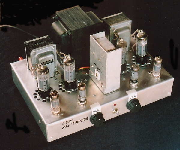
JBS-1 = Junk Box Special One. The 1960 Ferguson OPT were for an
amp meant for 12W
with 2 x 6GW8 or EL84.
I had collected about 20 used 6CG7 but found 4 were near new
condition to make the input stages
and LTP. I collected a number of 6CM5 in 1990s which were given
to me by ppl who no longer
wanted their collection of tubes. In most cases, the box of
tubes had mostly worn out tubes, but
some were new tubes in their 1960s boxes.
I used to lend the 2323 to people while I repaired their broken
solid state amps. A few did not want
to give the 2323 back to me when repairs were complete a week or
two later.
I concluded if the 2323 built from junk parts could change
people's minds about their budget Cambridge
and Creek amps, then what would they think with something made
with parts which were not junk?
I found out as time went by, and a small number of audio
enthusiasts agreed with me that their amps
must be tubed but of course most found reluctance to pay for
what they said they loved.
The best kept secrets about the 6CM5 :-
Although 6CM5 is a beam tetrode it will sound very good as a
triode.
When I first built it and compared it to a pair of Quad-II amps
I had repaired, the 6CM5 sounded better.
The 6CM5 was meant for line output in TV sets, and capable of
much more cathode current than other
power tubes like 6V6, EL84 and 6L6GC.
But anode dissipation is limited to around 18W in an audio amp,
so with two running Pda = 36W,
about 15W of pure class A is possible if the RLa-a anode load is
12k0.
6CM5 could be used as a single ended triode with anode load =
6k0 to give about 7W, and two in
parallel SET could give 14W+. The max class A triode efficiency
= 35%.
For tetrode mode, the best mode is with 20% CFB, Fixed Eg2 at
+250Vdc, Ea = 360Vdc.
The single 6CM5 has tetrode efficiency up to 45% so Po = 45% of
18W = 8.1W. For CFB the fixed
Eg2 can be +200Vdc, much lower than Ea and the tube works as
though it is in 20% UL mode, but
with 20% of Va-k fed back in series with the grid g1 Vac. The
result of CFB gives effective Ra less than
a triode but the Vg-0V is higher than for triode.
In pure beam tetrode mode, 6CM5 is very non linear like most
power pentodes of beam tetrodes.
This is due to the fundamental transfer function in a pentode or
tetrode where
Ia change = X x sq.rt ( Vg1 change cubed ) In triode mode or 40%
UL, such tubes have enough
anode Vac applied to the screen which acts a second control grid
so that the non linear function is much
lessened. See my page on basic-tube-1.html
and following pages.
In 1950-60 era, Philips produced two models of PA amps, for 120W
with 6 x 6CM5 and 60W with
4 x 6CM5. The tubes worked in pure tetrode mode with low idle
Iadc, so most Po was class B.
B+ was +330Vdc, Eg2 = 200Vdc, and one fixed bias -Vdc was
applied to all tubes. They had 20dB
GNFB, and their OPT was suitable only for "100V lines". The OPT
sec windings could not be arranged
to match 4r0 or 8r0. The 100V lines were connected many speakers
in the shop ceiling, each with a line
matching audio transformer. It is still done the same way now,
but amp is solid state.
The Philips amps worked very well because women disappeared into
shopping mall stores for hours and
re-appeared later looking strange and dazed and after having
spent all their husbands earnings on appalling
junk and bad food products they didn't really need - such was
the hypnotic combination of department
store and supermarket glitz with muzak playing softly, specially
composed by Fred Conman.
Keep the home triodes burning!
Back to Index Page