MANLEY-LABS
SNAPPER.
Completely re-engineered Monobloc Class AB 100W amps, made 1990s,
for about 80W per channel.
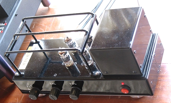
Fig 1. Two Snappers on a bench.
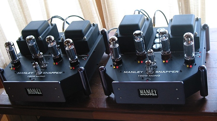
After many changes to original schematic,you can see the LED and
top of recessed smaller recessed
470uF / 450V electro caps which replaced the 1,100uF which were
about 135mm long, but which I found
were unreliable. See between the very good PT and very good OPT at
rear of amps. The original 1,100uF
electros which stood higher to look impressive. The smaller C
values made zero difference to how the amps
worked, or to the sound.
Red and yellow LEDs sit beside each EL34 output tube to indicate
correct biasing when both glow equally
bright. If an EL34 has Ia too high, the red LED glows brighter and
yellow turns off, and if Iadc is too low,
yellow is bright with red turned off. Anyone not liking the 5mm
LEDs could use 3mm and recessed down a
little more to reduce the "christmas tree" effect. The LEDS enable
bias setting without a voltmeter, and indicate
bias health with one glance.
Active protection prevents one or more output tubes causing
excessive current from PSU damaging an OPT,
and causing very expensive repair bills.
Fig 2. Close up of top of Snapper.
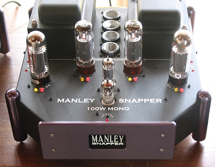
The owner used these amps to power Quad ESL989.
Fig 3. Input and driver stages....
Fig 4. Output stage....
Fig 5. PSU...
The original PSU had B+ of +560Vdc applied to EL34 in 25% UL mode
so both Ea and the
Eg2 were higher than used by many other brands.
The high Eg2 meant the Eg1 needed to be around -57Vdc and I found
the bias adjustment too
sensitive. The amps had been purchased from someone in Hong-Kong
who had found difficulty
with biasing, and had cooked several EL34 repeatedly, had gladly
sold the amps.
So the original amps overheat all too easily. Australia's high
mains voltage of 255Vac on many days
nstead of 240Vac does not help matters.
There are two PT primary windings each meant for USA 110Vac for
USA, and when in series the
Vac should be 220Vac. I installed R7, 410r, made up from 8 x 820r
x 10W wire wound resistors
in series and parallel to be 80W total rated. These are siliconed
to a chassis divider plate within
the amp and liberate 20W of heat.
The B+ voltage drop is 80Vdc to +500V applied to OPT CT, and this
is better tolerated by EL34.
The original OPT has ZR = 484 : 1. Load matches are 3k9 : 4r0, 3k9
: 8r0, and 7k8 : 16r0.
If we consider use with 4r0 speakers with a typical minimum Z of
3r0, the tube load is 1k5.
If B+ = +550Vdc, the EL34 will very easily overheat with loud
music signals.
4r0 speakers should NEVER BE USED!
For correct EL34 operation with B+ = +550Vdc, UL operation with
OPT screen taps on primary
should not be used. It is much better to have Eg2 = +400Vdc for
all Ea over 450Vdc. However, with
higher Ea there is need for higher primary load of OPT.
Loadline analysis will show that the 4 EL34 can produce 100W with
the Ea = +500Vdc and with UL
operation. The OPT should have primary load of 3k3 minimum and
with OPT ZR = 484 : 1,
so the minimum sec load = 6r8. Use of 8r0 speakers is then safe.
With each EL34 biased for Ia = 40mAdc, Idle Pda = 20W.
With sec load of 8r0, Maximum class A Po is 12W, and the maximum
class AB Po is about 85W,
and quite enough for anyone.
Fig 6. Active protection and bias condition indication...
The preamp used with Snapper was made on a chassis with same size
as a Quad-II power amp.
I have no schematic, but it used 2 x 6CG7 per channel with V1
giving gain, and V2 acting as cathode
follower after the volume control pot.
Fig 7. Integrated preamp.
This was made when I previously re-engineered a pair of Quad-II
amps for the same owner.
To
re-engineered amps directory
index