REFORMED
RCA AMPLIFIER
Edited 2017.
There are more ways than one to use tubes to make a fine
amplifier.
This page is about re-engineering a pair of RCA 30W ULAB1 amps
made before 1965.
Pictures 1, 2, 3 show samples I found online.
A customer brought me a pair to "fix up" so they could provide
better safety, less noise and
distortion, higher power and be usable for another 50 years. All
tubes now within the amps are
being manufactured in 2017.
Picture 1A. An original condition 1960 30W RCA monobloc amp
on bench, front view.
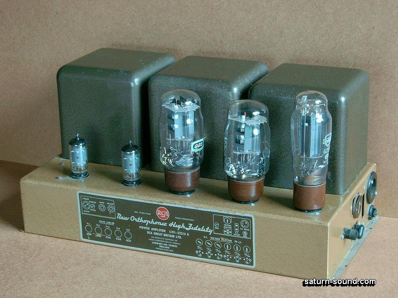
Picture 1A replaces the black and white photo I posted up in 2011.
Picture 1B. An original condition 1960 30W RCA monobloc amp
on bench, view each end
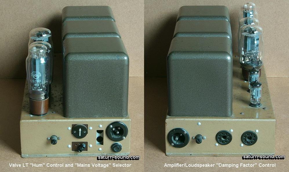
My thanks to the gentleman at saturn-sound.com.
The rectifier tube is GZ37 which is taller than the standard GZ32.
Watch out when servicing because if amps
are turned upside down on bench the weight of amp may rest on GZ37
and break the glass. Tape a block
of wood about 35mm thick to top of transformer cases before
turning upside down.
GZ37 has lower Ra and higher Pda rating to allow it to work with
lower series winding resistance of HT winding
but data says the first C = 4.0uF for 250mAdc, which is much more
than needed for 2 x KT66.
The original schematic below which I carefully re-drew shows GZ32,
and shows C = 10uF.
Both GZ37 and GZ32 are poor choices and GZ34 would be a lot better
if you really must use tube rectifiers.
The winding resistance of primary and HT secondary = 141r for each
diode, and it cannot be lowered, so use
of GZ37 will only slightly better reliability, with little rise of
B+. GZ37 and GZ32 are no longer made, and NOS
are expensive so the best tube to use will be GZ34, aka
5AR4.
Just remember that just the right value for cathode bias resistor
must be used for higher B+ than the +390V
in tables on the original schematic.
Notice the surface rust appearing through the paint on top of
chassis on left images. Many old amps with a fused
PU or OPT were replaced with cool running Squalid Stait amps when
the owner "upgraded" to stereo.
So the tube gear was just chucked out with rubbish, or just parked
in a garage or basement "to be fixed some day"
but were forgotten for 50 years. After 1960, tube audio gear made
a swift exit from many homes, and a minority
of listeners noticed their good music had vanished with the amps.
While being parked in damp garages and basements, the amps
rusted.............
Picture 2.
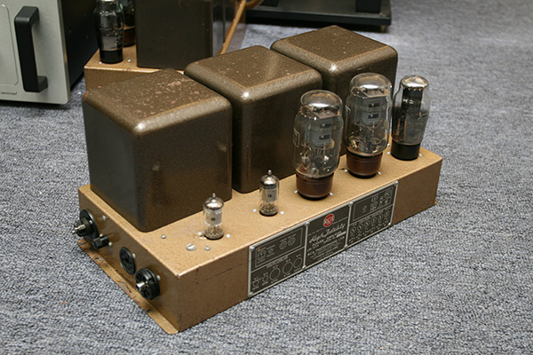
I found this picture online in 2017, by that well known guy,
gentleman@tubeheaven.com.he
The amp looks like it is in nearly original mint condition,
although it is unknown what mods have been done.
Picture 3.
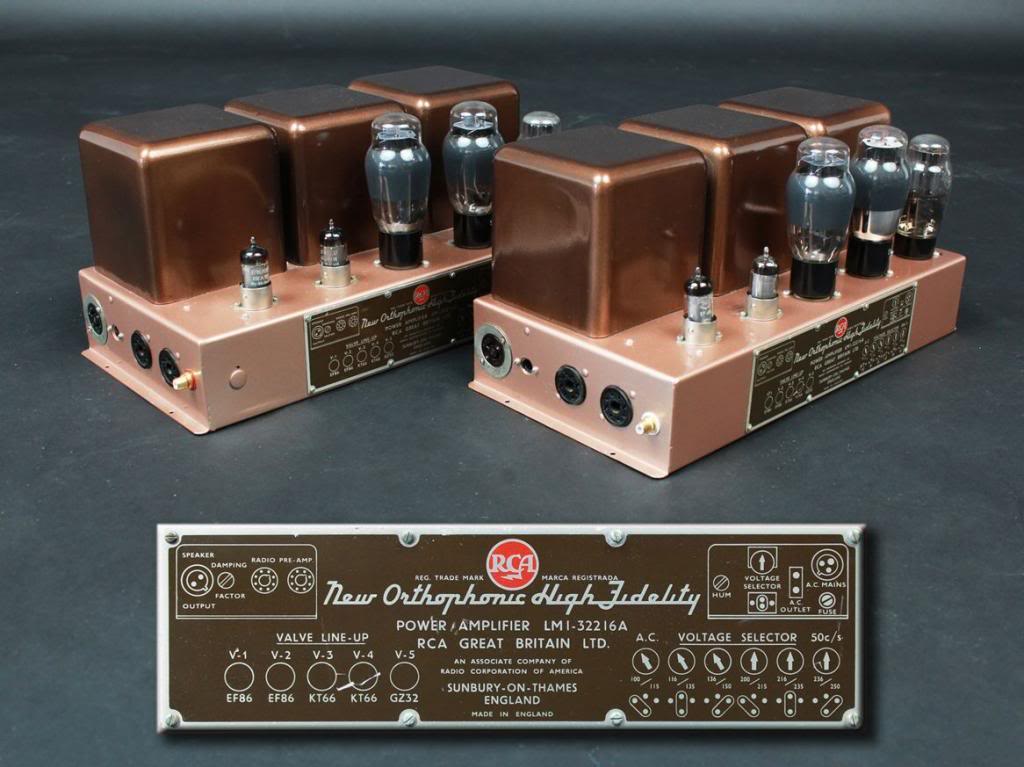
This a beautiful picture of jazzed up RCa amps from
somewhere.else@online in 2017.
IT IS NOT MY WORK !!
I could not find any accompanying information about what may or
may not have been done to the schematic.
The output tubes look like NOS large bulb 6L6 for Mr and Mrs
Poshandrich.
This pair of amps have "Made In England" on label and by 'RCA
Great Britain' which was owned by RCA
in USA. The amps probably were assembled in UK with USA made parts
to escape the possible ravages
of paying a trade tariff on imported amps which competed with
Quad, Leak, Radford, and other UK makers.
You may assume these products were subject to all sorts of trade
restrictions and politically inspired rules
and regulations. AFAIK, RCA did not make EF86; it is not in my RCA
Receiving Tube Manual. Maybe all the
tubes were made in UK. The amps have UK flavour, UK aroma, and
have said by Mr XYZ to be a mutated
Quad-II, but I doubt the Quads would sound any better. The RCA are
more ruggedly made.
Each "30W" monobloc amp was known as RCA Orthophonic High Fidelity
amplifier. The general condition
of the pair I worked on was fair, and one looked OK but the other
has such bad paintwork and rust
I decided on an all black finish after a sanding down as must as
possible for both which was much cheaper
complete dismantling and sand blasting then repainting with
"crackletone" paint like original.
They may have been parked for 40 years in a damp basement.
One amp was purchased years before stereo listening became
popular. The other was bought after stereo
came with LPs, and its chassis size and transformer cases were
slightly different, but nobody notices it.
There were minor differences of connection terminals but they both
had the similar schematic using
2 x EF86, 2 x KT66, 20% UL OPT, and GZ32 rectifier.
I have fitted an RCA input socket and 4mm semi recessed banana
sockets for speaker cables which must
have banana plugs only. All other odd holes have been blanked off
with sheet metal. Only 1 of two octal
sockets for preamp power has been retained, but nothing is
connected to it inside because the amps are
to be used with a non RCA brand and stand alone preamp.
The amps were lethal because they lacked chassis bottom covers on
chassis. There was never any
ventilation of area under chassis. There were no covers over the
tubes. I have seen people get a severe
shock when moving old tube amps while they are plugged into mains
and turned on. I made bottom sheet
steel bottom covers with plenty of drilled holes and fitted bolted
on timber support feet at each end to aid
ventilation under chassis.
Fig 1 below is my re-drawn copy of the original 1960 schematic.
The original .jpg image of schematic was
found online and was was typical poor legibility without enough
dots per inch, so it was impossible to read
all the fine print, or enlarge the schematic and clean it up
digitally. The only way to clean up old schematics
is to re-draw them entirely in MS paint. The XP Paint or W7 Paint
is easier to use than the latest MSPaint in
W10.
Does anyone know where a better simple drawing program is to be
found and which is free????
The original schematic is similar to that used by Dynaco who used
the RCA schematic but using a 6AN8
triode pentode so the input + drive amp needed only 1 x 9pin mini
socket.
I see no reason to ever rebuild any amp using the RCA design
because far better performance is possible
with a pair of mini nine pin twin triodes such 2 x 6CG7. But
further down this page I show a good 2017 amp
version with EF86 as an input triode with 6CG7 LTP driver,
slightly simpler than the 2014 schematic for
the 2 x RCA amps I re-engineered.
Fig 1. 1960 30W amp re-drawn 2017.
This is my re-drawn 1960 schematic for RCA 30W UL monobloc amp.
A previous edition of this page in
2014 included a poor quality .jpg image posted online by
sumphule@crapistika.com.fu who worked for
Richard Cranium Doings P/L, a crusty old UK company using dodgy
methodologies ;-/
Since 2011, I have not been able to find anything better. So in
2017 I spent a couple of days examining the
old schematic from 1960, labelled "Fig. 6. Power Amplifier,
Schematic". This may have been one sheet of
maybe more than six illustrations in the RCA manual which would
have existed in 1960. I have searched for
the RCA 30W tube amp manual, but found nothing.
The original schematic had tables for Ea and Eg2 and Ia for all
tubes. B+ for KT66 anodes was +390V and
B+ for screens was +295V. We may assume B+ at OPT CT = +400Vdc,
and there is a Vdc drop of -10V across
each 1/2 primary of OPT. The Ek at common cathodes at R18 was
+25Vdc. It was difficult to read the R18
resistance value but it looked like 260r, but probably was 250r.
This R18 value meant each KT66 idled at Ikdc
= 50mAdc.
Screen Eg2 = B+ less Ek = 295V - 25V = 270Vdc. Anode Ea = 390V -
25V = 365Vdc. Total Idle Pda + Pdg2
would have been = 17.8W, considerably less than 25W max rating for
idle Iadc for KT66.
I think that before RCA adopted the use of 20% UL taps for screens
on its OPTs, they would have used KT66
in plain beam tetrode with the Vdc shown on the table below
schematic. The set up would have been consistent
with information in data sheets for MOV KT66 for use in beam
tetrode mode with fixed Eg2.
The old schematic had screens connected to UL taps.
It appears RCA had forgotten to change Vdc for KT66 on the table
on schematic sheet "Fig 6".
R18 remained at 250r, and had not been changed to the higher 360r
to compensate for Eg2 = Ea = 400V
for UL.
I gutted the 2 amps I re-engineered before I began re-building,
and I don't recall the value of R18.
The UL connection means Eg2 = Ea, and if R18 = 250r, the Ikdc of
each KT66 will be about 60mAdc, with Ek
= +30Vdc approx. The PT and choke and GZ32 give a PSU with fairly
high Rout, perhaps 500r, so that if Ikdc
increases by say +20%, the B+ at OPT CT will never reach +390V,
but would more likely be +375V.
Ea = 350V, and if Ikdc = 60mAdc, idle Pda = 21W, an increase of
+18%. The amount of initial pure class A Po
will increase from 9W to 13.3W, but class AB1 Po max will much
reduce because of limited Va swing, and
30W max would be difficult to get.
Let us determine alternative Rk for cathode biasing for KT66 in UL
mode with Ea = Eg2 = 400Vdc.
We may assume that the RCA PSU with GZ32 plus CLC filter of
10uF+5H+10uF can produce B+ = +400Vdc
at about 105mAdc for 2 x KT66, 2 x EF86, but without powering an
RCA pre-amp and AM-FM radio tuner.
The 350V-0-350V HT winding with GZ32 will give +490Vdc without a
load, and at least +400Vdc with 100mAdc
for 2 x KT66, and 4.5mAdc for the 2 x EF86.
You may find few electrolytics would withstand nearly +500Vdc for
very long, including all those
rated for 450Vdc when working. But most with 450V working rating
will tolerate +500Vdc for the 10 seconds
while KT66 warm up. The KT66 warm up more slowly than most
indirectly heated tube rectifiers so the B+
will soar to maximum unloaded B for a few seconds before being
pulled low by KT66 to the wanted safe B+
level.
Silicon diodes have low on resistance < 1r0, which means HT
need only be 310Vac giving +437Vdc max, and
the total PT winding resistance and choke can be up to 200r and
you still get B+ = +400V with 124mAdc.
Before electrolytic caps became reliable enough, many amps use
capacitors with paper and metal foil immersed
in highly poisonous types of electrical oils in well sealed cans.
I had some old oil-caps for 1,000Vdc x 10uF and
they were 100mm x 50mm x 100mm.
For UL, KT66 Ea = Eg2 and will be approximately +365V because we
can expect Ek to be about +35Vdc for
50mA in each tube.
To calculate Eg1 for any tetrode of pentode with Ea = Eg2, or any
triode without a screen,
Eg1 = [ ( Triode Ra x Ia+g2 ) - Ea ) - Ea ] / triode µ.
Ia+Ig2 is the wanted total dc for anode + screen at idle, equal to
Ikdc.
The triode Ra is calculated Ea / Ia from observing the Ra curve
for Eg1 = 0.0V.
RaT = Ea change between 0V and point where Ia = wanted idle Iadc /
wanted Iadc or close to it.
For KT66 in triode mode at dc conditions, Ra = 80V / 50mA =
1,600r.
For any chosen value of Ea and idle Pda, the formula becomes
Eg1 = [ ( triode Ra x { Pda / Ea } ) - Ea ] / triode µ.
For this case, Eg1 = [ ( 1,600 x 18 / 365 ) - 365V / 7.85 =
-36.44Vdc.
The Rk can be also calculated without first calculating Eg1, or
Ikdc. If we know permissible idle Pda and
we can estimate Ea, then we can work out Iadc = Pda / Ea.
For Ea = 365V, Pda = 18W,
Rk = [ RaT - ( Ea x Ea / Pda ) ] / µT.
For this case, Rk = [ 1,600 - ( 365 x 365 / 18 ) ] / 7.85 = [
1,600 - 7,401.4 ] / 7.85 = 739r.
The Ikdc should be = Pda / Ea = 18W / 365V = 49.32mA, so Ek = 739r
x 49.32mA = 36.44Vdc, which
is what we calculated for Eg1 above.
The B+ required for Ek = +36.44V and Ea = +365Vdc = 401.44Vdc, and
this is close enough to settle for +400Vdc.
The MOV data sheets with KT66 triode Ra curves will show that for
Ea = 365Vdc, Ia = 49mAdc, Eg1 = -35Vdc approx.
For 2 x KT66 with common Rk, then Rk = 739r / 2 = 370r. I show R18
= 360r using 2 x 18r x 10W ea in series.
From the live end of R18, I have 10r0 to each cathode which allows
easy measurement of Ikdc in each KT66.
The Eg2 screen Idc may be measured by Vdc across R19 and R20, then
divide by 220r. I found Ig2 for most output
tubes did not vary much more than others by +/- 1mA, even when
tubes were old, so if Ikdc of each KT66 or other
output tube is equal, then Iadc in each 1/2 of OPT primary will be
equal within +/- 3mAdc, and sound will be fine.
--------------------------------------------------------------------------------------------------------------------------------------------------------
For beam tetrode, anode B+ = +400V, screen B+ = +300V.
For where Eg2 is a lower +Vdc rail than for anodes, the lower Eg2
reduces Ia. Thus the negative Eg1 bias must be
reduced to make grids less negative to increase Iadc to the same
level as for where Eg2 = Ea.
Above, we showed that with B+ = +400V, Ea = Eg2 = +365V, Ia was
49.3mAdc, and Ek = +36.4V.
Let us consider 2 x KT66 in tetrode mode with anode B+ = 400V, but
Eg2 is -100V lower than Ea.
reducing Eg2 -100V reduces Ia x theoretical amount = Eg2 change x
screen gm.
The screen gm = 1V / triode Ra = 1V / 1,600r. The reason why g2 gm
= 1/ triode Ra is because the screen g2
works just like a grid that is separate to anode, and it exerts
electrostatic voltage field change on the electron
stream just as it would if it was an anode which had gm = 1 / Ra,
and no screen existed. Anodes have gm.
Basics are explained in basic-tube-1.html
and following pages.
So, theoretical reduction of Ia = -100 x 1/1,600 = -62.5mA. This
is a theoretical figure, because we began with Ia
= 49.3mAdc. If we reduced the Eg1 bias to mage grid less
negative, the Iadc could be restored to +49.3mA
by having Eg1 = Ek = 62.5mA / gm g1. KT66 gm g1 = 4.9mA/V, so Ek
change = Ia change caused by
Eg2 change / gm g1 = 62.5mA / 4.9mA/V = -12.7V.
The Ek must change to approximately 36.4V - 12.7V = 23.7V. We
must NOT let ourselves to be exact because
the KT66 and other tubes have non linear change of µ, gm,
Ra.
Let us assume the Ek may be +25V. If screen B+ = +300Vdc, then
Eg2 = 275V. Ea will be about +375V.
For where Eg2 is lower than Ea, calculate Eg1 first as
Eg1 = [ ( RaT x Pda / Ea ) - Eg2 / triode µ,
where Ra is at Ra curve for Eg1 0.0V, and from 0.0mA to
approximate Iadc at idle. This was worked before,
= 1,600r.
Pda is allowed idle Pda+g2 = 18W, Ea = B+ - approx Ek = 375V,
Eg2 = screen B+ - Ek = 275V,
triode Ra at idle Ea x Ia = 1,600r.
For this case for 1 x KT66, Eg1 = [ ( 1,600r x 18 / 375 ) - 275V
] / 7.85 = [ 76.8V - 275V ] / 7.85 = -25.25.
Therefore Ek = +25.25Vdc.
Ia+g2 = Pda / Ea = 18W / 375V = 48mAdc, so Rk = 25.25V / 48mAdc
= 526r.
Once set up, it will be found that Ig2 screen Idc will be less
than where Eg2 was +370V. The screen dc input
current is another non linear property of the tetrode or
pentode. We may find Ig2 with Eg2 = 275V to be 4mA,
about 2mAdc less than for Eg2 = 375V. Thus Iadc may be 44mAdc,
Ig2 = 4mA, Pda = 16.5W, Pdg2 = 1.1mA,
for a total Pda+g2 = 17.6W.
Thus we can afford to reduce Rk to 500r, and we may use 2 x 1k0
each 5W in parallel.
For a single common Rk, use 4 x 1k0 in parallel for 250r.
The MOV data sheets for KT66 say separate Rk plus bypass caps
should be used for a pair of KT66.
RCA and many other makers, ( even Quad ) did not agree, and used
a common Rk. Some employees of
many tube amp manufacturing companies earned their living by
saying NO to engineers. Wars erupted in
the offices of companies. Egotistical engineers wanted their amp
to be adopted as best in the world and
weighing 15Kg, with 269 parts.
The Maniacal Economic Sadists ( MES ) delighted shareholders by
reducing weight to 8Kg, and parts
count to 200. The quality thus extracted was not a waste
product, but a very wise investment of monies
"saved" because the tubes wore out sooner, and needed more
frequent replacement. A definite win-win
solution. RCA made tubes, and their prosperity depended on
selling as many as possible, so they made
sure that happened.
The sooner OPTs and PTs fused their windings, then the sooner
many ppl changed to more expensive
new amps and CE0's chuckled all the way to the bank.
The MES always win the wars, the ego driven idealists always
lose.
It is all going under your nose right now for 1,001 products so
that globalization makes globally rich
get globally richer. Fortunately, a few of us do not want 2077
to ever occur, and don't mind 2017, while
realizing the invention of UL in 1957 was a nice little step
forward, and the extremists think 1927
was a really good year when the 300B was conceived.
---------------------------------------------------------------------------------------------------------------------------------------
What happens if mains Vac changes +/-5% ?
In Canberra, Australia, nominal 240Vac mains can vary down to
235Vac on a very cold winter night
when demand is high. This is a change of -2.1%, and I've never
seen mains drop lower. The mains
could go to 228Vac, and the amps would still run OK, and cooler,
but produce 10% less Po. Filament
heating would run a little too low at 5.54V instead of 6.3V.
The big worry is where mains Vac goes high. I often measured
mains at 252Vac for times of low
demand, so mains is +5% higher. If any amp has been designed to
give wanted working Vdc and heater
Vac with 240Vac mains, then +/-5% mains variations should not
cause any overheating problems.
The main risk to tube amps occurs where B+ rises, which makes
the whole amp run hotter. But even
with correct mains Vac, hot summer days brought indoor
temperatures up to 30C in 1960 when virtually
nobody had air-conditioning, and amp chassis could be an
alarming 50C, with mains PT too hot to touch.
High mains just made things worse.
With RCA 30W UL amps with common Rk = 360, the PT primary should
be 230Vac to make a nominal
350V-0-350V at HT sec. Australia's nominal mains voltage =
240Vrms. If this rises +5% then mains
= 252Vac, and the nominal unloaded HT will rise to 383V-0-383V,
with maximum B+ = +541Vdc.
( This worried me when I re-engineered the pair of these amps. I
used IN5408 diodes instead of
tube diodes and I replaced each original B+ filter cap with 2 x
470uF x 350V rated in series to avoid
excessive Vdc causing caps to short circuit. )
I always found GZ34 gave slightly higher B+ than GZ32. The data
for GZ32 says 60uF can be used
for the rated max Idc = 250mAdc, which is twice the Idc rating
of GZ32, so GZ34 is better than GZ32.
I found GZ32 is more likely to arc over internally when its
lower peak Ia ability is inevitably exceeded
when a faulty KT66 or both draw a total of 200mAdc.
With Si diodes the B+ rises about the same % as any mains Vac
rise. But with individual 820r at each
cathode of KT88 which I used, and with idle Iadc 47mA The Ra is
effectively about 7k0 and a +21Vdc
rise of B+ increases Iadc by only +3mA. I have KT88 with idle
Pda = 18W, and their max Pda rating
is 42W, twice that for KT66, so mains changes have negligible
effect on operation.
Effective Ra of each KT66 with Ea = Eg2 and with cathode biasing
Rk is calculated :-
Ra' = Ra + [ ( µT + 1 ) x Rk ] where Ra is the Ra calculated
from tangent line to Ra curves at idle Ea x Iadc,
µT = triode µ, and Rk is for one tube.
For KT66, where Ra = 1,600r, µT = 7.85, Rk = 720r, effective Ra
= 1,600 + [ ( 7.85 + 1 ) x 720r ]
= 7,972r, so two give a load of 3,986r. The minor load of input
tubes may be considered as a resistance
= B+ / Iadc = 400V / 4.3mAdc = 93k. The total dynamic load on
PSU = 3,986r // 93k = 3,820r.
KT88 will have similar effective loading on the power supply,
but will tolerate high mains Vac much better
than KT66.
To avoid overheating on hot Australian summer days with high
mains, there are options :-
Option 1 = Use separate Rk each 820r.
Option 2 = Add 100r x 10W in series between each end of HT
winding and use GZ34.
Option 3 = Do both of above, and adjust series R to wanted
result.
Option 4 = Remove tube rectifiers and socket, use 2 x 1N5408
diodes to replace each tube diode,
then do option 1 + 2 with adjusted R between HT windings at
diodes to prevent B+ exceeding
+425V.
Option 5. Do option 1 + 4 and replace KT66 with KT88 or 6550
without having Iadc higher than 50mAdc
meant for original KT66.
Nearly all above options are entirely unacceptable to the
purists who could like things kept as close as
possible to how things were in 1960. I don't share their
nostalgia, and see no reason why old solidly
made amps should not be liberated to give better Hi-Fi and more
reliability.
All old carbon composition resistors and paper+foil coupling
caps and electrolytic caps should be replaced
with nearest standard values, eg, 22k instead of 20k, 0.27u
instead of 0.25u. C12+ C13 were 10uF. C8 was
8uF. All 3 could be 33uF, but they need to have high Vdc surge
rating of 500Vdc at least, and the safe option
is to use 68uF x 350V in series pairs to make 34uF, with 150k 2W
across each. A GZ34 will cope OK with
C load of 34r. The size of the new caps is not a problem. There
is plenty of room under the chassis.
Using GZ34, or Si diodes with larger PSU caps will raise B+ at
OPT CT but it is all quite OK.
Cathode R+C gives automatic regulation of Ikdc for all tubes.
With KT66 output tubes sharing one bias Rk,
the automatic regulation benefit is nowhere near as good as
having separately biased with its own Rk+Ck.
With a single shared Rk, the Ikdc and thus Iadc can become very
unequal if one tube ages before the other
and changes to conducting more Idc than the other. Leak used
separate Rk +Ck biasing for output tubes.
I worked on countless amps with a single Rk for a pair or many
more output tubes, or there was only one
value of -Vdc applied to all tubes. They all had very different
Iadc, and when I used individual R+C for
each tube or a bias adjust pot for each tube, tubes lasted much
longer and sound was better.
In MOV data for KT66, the expected tube life = 8,000 hours. The
conditions are stated.
If tubes have been used 5.5 hours per night for 4 years, it is
8,000 hours. But some will last 5,000 hours
or 10,000 hours. At low Idle Pda and free from traumas caused by
teenagers, old faulty coupling caps and
resistors, and turning on and off 6 times a day, you can get
much longer life.
I knew one fellow who was using EL34 some 45 years after he'd
bought them for an amp he built in 1960
which used Ea = 270V and Ikdc 56mAdc, with Pda lower than
normally used for EL34.
------------------------------------------------------------------------------------------------------------------------
Useful formulas for setting up output tubes :-
Ikdc = B+ / [ ( { µT + 1 } x Rk ) + RaT ].
This allows you to calculate Ikdc for where you know B+, triode
µ, triode Ra, and Rk.
Once you know Ikdc, you can work out Ek, and then Ea, and then
idle Pda = Ikdc x Ea.
B+ = Ikdc [ ( { µT + 1 } x Rk ) + RaT ].
This tells you what B+ is needed where you know Ikdc, triode µ,
Rk, triode Ra.
Rk = [ ( B+ / Ikdc ) - RaT ] / [ µT + 1 ].
This gives you Rk where you know B+, Ikdc, triode Ra, triode µ.
These 3 formulas are accurate for Iadc being between 30mAdc and
110mAdc which covers the range
of likely idle Iadc for KT66.
----------------------------------------------------------------------------------------------------------------------
So far, calculations are for UL or triode strapping of beam
tetrodes, or where Eg2 = Ea.
But where screen B+ supply is say 100Vdc less than an anode B+
supply, then the -Eg1 is calculated
-Eg1 =[( Iadc x Ra ) - Eg2 ] / µ
where Ra is for triode Ra for Eg1 = 0V and calculated between
0.0mA to wanted Iadc, Ea = Eg2 = Vdc
between anode and cathode, and µ at wanted Iadc.
The original RCA 30W did not have UL taps. The KT66 were set up
in pure beam tetrode with
anode B+ = +390Vdc, screen B+ = 295Vdc.
Therefore Ek for cathode biasing will be less than where Eg2 =
Ea as in case of having UL taps.
For B+ = 390V, screen B+ 195V, expect Ek = +24Vdc, and not +37V
as for UL.
The Rk could be 500r x 5W per tube.
This estimated solution is consistent with R+C values shown on
old schematic from RCA and also
with MOV data for class AB1 use of KT66 in beam tetrode mode.
--------------------------------------------------------------------------------------------------------------------------------
The the old original RCA 30W UL amps have TWO GNFB networks. One
gives conventional
series voltage GNFB via R8 24k from OPT sec to V1 cathode. The
other is for adjustable positive
or negative global current FB via R22+R23 and adjust pot RV1
plus R21 to R6 39r at V1 cathode.
The original 1960 amp schematic shows OPT strapped for 16r0, and
I estimate there is about 29dB
GNFB with a 16r0 load. This is a lot of GNFB, and if the amp is
strapped for 4r0, the output Vo is
halved, and amount of GNFB is reduced to about 23dB, which is
still a lot.
Without any load, the output stage gain increases 8dB, so GNFB
increases to 37dB and 31dB with
load settings for 16r0 and 4r0.
These maximum possible amounts of NFB are far too high to allow
unconditional stability, and you
would expect they would oscillate at LF and HF without a speaker
connected, and any hint of
capacitance across the output would cause HF oscillations.
Nearly all 1960 tube amps did this.
Negative global current FB will slightly increase Rout, and
improve stability. NCFB is maximum where
RV1 wiper is turned to top of the pot.
Positive global current FB will lower Rout to less than achieved
with the voltage GNFB, and maximum
Rout reduction is where RV1 wiper is at bottom of pot.
Positive current FB increases THD slightly. I have experimented
with PCFB in other simple PP amps.
I found I could reduce the Rout to zero ohms and then to make
Rout NEGATIVE, which means that
if the ohm load is reduced, the output Vac increased, and I
found it possible to easily make the amp
oscillate with a very low load. This is a horrible amp property.
But while the Rout was positive, ie, Vac reduced with lower
load, then expect a DF > 10.
The whole experience of PFB had me conclude it was a horrible
thing to have on any amp, and I
abolished the original variable Current FB network when I
reformed these 2 amps.
But I did allow some negative current FB at HF which helped
reduce ringing on square waves.
The manufacturers of 1960 were very keen to have lower THD
measurements than any one else
to make a claim of better quality to sell more amps. Large
amounts of NFB were not uncommon,
but nearly all old amps I have ever worked on were highly
unstable and were likely to oscillate at
LF below 10Hz and at HF above 20kHz, and they could not easily
be made to give wide bandwidth
and unconditional stability. All oscillated without a load
connected.
The schematic has no information about change to NFB network
when the OPT strapping was
changed. This feature was also and normal for many old amps, and
involved a trip to a technician
with a soldering iron and perhaps some idea of what he was doing
when sober.
The NFB networks should be changed to ensure the same amount of
NFB is applied for the 3
strapping patterns for 4r0, 8r0 and 16r0. I have never seen a
copy of the manual for the amp.
There are no R+C Zobel networks on original schematic to reduce
HF gain and phase shift
above 10kHz to prevent RF oscillations with NFB. At OPT, C10+C11
2n2 shunt 80% of each
1/2 OPT primary winding and screens are fed through 220r. The UL
screen taps are at 20%.
The 220r + 2n2 are not Zobel networks and act to increase phase
shift and make the amp
more likely to oscillate at RF rather than less. There should be
about 2k7 x 5W in series with
each 2n2 to give the OPT an R load above 30kHz, and not a C
load.
When I re-engineered this pair of RCA 30W amps, I quickly
realized how many original features
were less than optimal and how unsuitable the amps would be if
someone wanted to use use
speakers with good cables with 4mm banana plugs at each end or
use a stand-alone integrated
preamp with say 6 switched sources, digital radio, AM-FM
tuner, sound card, phono preamp,
CD player etc. It is probable that almost anything would be
better than an original RCA preamp
meant for these power amps.
I did not have time to examine and record the value of each and
every working voltage and current
or the value of R18 after deciding to completely remove all
circuitry boards and minor parts to
allow total re-building. RCA have been known to use BETTER
input/drive amps than the use of
2 x EF86. EF86 or identical 6BK8 are not included in my RCA
Receiving Tube manual. It is possible
RCA obtained supplies of EF86 from Mullard in UK. The small 7
pin 6AU6 pentode was more
commonly used for RCA audio amps.
Fig 1. Repeated. 1960 30W amp re-drawn 2017.
The only way this amp could ever make 30W is where the output
load is less than 1/2 the
strapping value, ie < 2r0 for 4r0 strapping or < 8r0 for
16r0 strapping, and the amp is driven
very hard, in a manner unlike any real normal use.
The amp has TWO global NFB loops. One is for Global series
voltage NFB and is quite conventional with
Vac from OPT sec Vo fed back to V1 cathode via R8 24k, R7 1k0.
R5 gives combines with R7+R8 to form
2k0 Rk for V1 which gives 6dB local current FB to V1. R6 39r0
may be ignored until I talk about the global
current FB.?????????????
The V1 EF86 is set up with a feeble amount of anode Idc, but
quite enough to have gm = 1mA/V which
gives gain of 174 without the bootstrapping of R4 220k and grid
R9 680k.
The Rout from V2 cathode is low, and used to bootstrap the top
of R4, so that gain of V1 has effective
RLa raised to and gain is 1,164, somewhat amazingly high, for
any single tube, but possible with a
pentode with high Ra and enough gm. The 2k0 for V1 Rk reduces
the V1 gain to 538.
V2 is a concertina phase inverter, CPI, aka split load phase
inverter. It is EF86 in triode mode with healthy
Ia = 3.1mAdc. It has µ 33, Ra 18.3k, and makes a very nice
linear triode. Its RLa = R10 20k // R14 560k
= 19k3. RLk = R12 40k // R3 40k // R15 560k = 19k3.
Bootstrapped R4 220k has negligible loading of V2 cathode so the
opposite phased grid Vac to KT66 are
well balanced. The gain of V2 = 1.83Vac where 28.5Vac at v2 grid
gives 52Vac between anode and
cathode, ie, two phases of 26Vac each. V2 acts like a buffer
between V1 and KT66, and input resistance
to V2 grid is extremely high with low capacitance.
It is unknown how much THD is produces by V1, and it will be
impossible to measure it easily, or plot load
lines to determine it because the anode load = 2M0, and at
28.5V, the anode Iac = 0.0145mA, ie, 14.5uA.
I calculated that with original values for R8 for GNFB, there is
29dB GNFB. There are no Zobel networks
or shelving networks to reduce open loop gain below 20Hz or
above 20kHz. If the amp has no load, the
output stage gain will increases from the 8.8 shown to the UL µ,
about 36, or by +12dB. Therefore total
GNFB increases to 41dB without any OPT sec load, and I suspect
oscillations at LF and HF will both occur.
With no load, there is no current FB to have any reduction
effect on oscillations.
The Global Current feedback can be adjusted by RV1 to give a
small amount of NFB when pot wiper is at
high position, and a small amount of positive current NFB with
wiper at low position.
R22 and R23 are in series with the load from OPT sec coil. So
they waste a little Po from the amp, and
this wastage will be highest when amp is strapped for 4r0. The
current FB is fed to V1 cathode via R21 220r
to R6 39r.
RV1 may be set so its Vo at wiper = 0Vac, and the 39r adds a
negligible Vac to bottom of R5 2k2.
So the amp may be analyzed without considering current FB
effects of the small Vac applied to R6 39r
which cannot be more than 0.055Vac+ or 0.093V-.
The current FB is wide band, and just what exact effects it has
are unknown, except that it changes the
amp output resistance, ie changes damping factor, perhaps by +/-
6dB.
All my experiments with wide band positive current FB led me to
conclude it was quite useless and if the
load was a short circuit, then voltage FB reduces to nothing,
and there is much positive current FB which
could make an amp oscillate at full Po into a short circuit,
causing KT66 destruction. PCFB has the effect of
increasing THD but has the magical effect of lowering output
resistance. Lots of PFB will reduce Rout to 0r0,
ie, DF becomes infinite; a lower load causes no Vo drop. A
little more PCFB will make Rout negative, ie,
Vo rises when load ohms are reduced. Well, the amp cannot keep
the same Vo it has at 24W into 16r if
load = 1r6. But even with level reduced to 1Vo with 16r0, the Vo
may reduce -3dB to 0.76V without PCFB.
The PCFB could make Vo = 2V with 1r6. Would anyone want this?
well no, so I guess RCA have thought
this through to not allow enough PCFB to cause Vo to rise with
reduced RL. But would the RCA amps work
with Quad ESL57? these have Z = 32r0 at LF, about 8r0 at 2k0,
and only 1r8 at 18kHz.
There are very few amp makers who supplied adjustable damping
factors. Most speakers are designed to
work with amp Rout < 1r0 regardless of what their Z is at any
F.
I cannot think of any modern amps with variable damping, mainly
because the Rout is typically < 0.1r0
with solid state where zillions of dB of NFB are used to correct
all forms of distortion.
IMHO, the variable DF on RCA amps would offer most people
nothing they would easily hear, and the
variable DF is just a valueless feature which wastes power, and
which is not needed, and can thus be
abandoned.
<
RV1 and R22+23 may have been more useful with KT66 set up for
pure beam tetrode where beam
tetrode Rout is much higher than when UL connection is used. All
audio amps need only have have
Rout < 0.1 x output load for a damping factor of 10.
The only use I found for global current FB was to apply some
NEGATIVE CFB to make the HF stability
better with a fixed R+L network that gave increasing NCFB above
10kHz with added phase advance to
correct the phase lag of the open loop so that phase of GNFB
applied at V1 cathode has phase closer to
input to prevent the NFB from ever becoming positive due to
phase difference between input and NFB.
The principles of how to make a good OPT are detailed in RCA's
Radiotron Designer's Handbook, 4th Ed,
1955. This gives the details of D.T.N Williamson's famous design
for 1947. just about all the manufacturers
after 1947 routinely ignored what RDH recommended, and including
RCA themselves, in this RCA 30W
model.
The RCA 30W OPTs do not have the quality seen in a few hi-end
amps, and in one pair of DIY amps
where the DIYer spent twice normal of low-fi OPTs to get a pair
of highest grade from A&R in Melbourne,
and encased in die cast cases. These A&R had 100kHz
bandwidth, with terminals facing down into
chassis space. They were better quality than anything in
Quad-II, Dynaco, later Leaks, etc.
The output tubes limit Va and Vk swings to +/-37Vpk because
V3+V4 grid current reduces grid input
resistance from megohms to about 2k0 when Vg tries to go
positive above Ek.
Without V3+4 plugged in, V2 can produce Va-k = +/- 80Vpk or +/-
40Vpk at anode and at cathode.
This is 28.3Vac at anode and cathode, and just above the level
of 26Vrms where clipping begins due
to grid current. Increasing B+ from +340Vdc to +375Vdc will
increase possible Vac max to 31Vac,
and slightly reduce the V1+V2 THD. One could use a 12AU7
paralleled instead of EF86 with B+ 375V
and idle point at 150Vdc x 3.7mAdc which will give 38Vac at
anode and cathode without limiting by
V3+4. The THD will be similar to EF86. The open loop gain of
V1+2 and this total amount of NFB
would reduce about -3dB because there is less bootstrapping to
V1 RLa, effectively reducing V1 gain.
But as it is with V3+4, plugged in, the output stage clips just
before V2 clips with output load = strapping value.
If the load is less than strapping value, V3+4 Vg cannot be
increased because of limiting by Ek = 36Vdc.
Heavy overload will produce asymmetrical clipping because V2
anode Rout = 19k, and cathode Rout < 1k0.
This does not matter because hi-fi amps are never driven into
hard overload like a guitar amp.
In 2016, someone with a pair of these amps still in original
condition asked me how to strap the OPT to
suit 8r0 speakers. There is no strapping information on the
original schematic.
The original schematic above was in early version of this RCA
amp, and seems to have input and
driver schematic to suit pure beam tetrode which would have been
pre 1955. The UL taps would have
appeared after 1955, as well as the later change to use of 3 sec
windings on OPT.
Here is a bit more about basic amp operation and with strapping
patterns.
Fig 2. RCA 30W ULAB1 OPT strapping patterns, basic
operation.
Fig 2 shows an abbreviated amp schematic with OPT strapping for
early or later versions of RCA 30W amps.
RCA gave owners the function of the "variable damping control",
I show 16r0 strapping and I assume load
= 16r0 load as in Fig 1 schematic for 1960.
Working Vac shown are with RV1 set so that 0Vac is at top R6
39r, ie, the RV1 pot is adjusted for neutral
effect on normal series voltage GNFB.
--------------------------------------------------------------------------------------------------------------------------------------------------
Minimum mods for 1960 RCA 30W ULAB1 amp.
Fig 3. SHEET 1, Simplest mods for RCA amp.
Fig 3 shows a number of changes to the original RCA amps to be
able to use them more easily with a
stand alone integrated preamp. None of the R+C numbers are the
same as in Fig 1.
The PSU with minimal mods is below.
Strapping of the OPT is shown in Fig 2.
Fig 3 shows the THREE different R+C used for the SAME 20dB of
GNFB with each change of OPT strapping.
Any mistakes made with strapping and NFB network settings will
NOT be forgiven by the God Of Triodes, and
you may generate noise, then smoke, silence, and a huge repair
bill.
The R values for RLdc for V1 anode and screen have been changed
and cathode Rk changed to give higher
Iadc and Ig2, and to allow normal GNFB application with lower R
network R12 + R9. R9 is taken to a small
air wound choke of about 5 turns 1.2mm dia enameled Cu wire with
internal dia 10mm. This L should be
about 0.4uH. The speaker is in series with the 4uH and above
10kHz the speaker current generates a global
negative current feedback Vac which is applied to bottom of R9.
The phase of this Vac generated by current is advanced to
compensate for the lag of phase in the amp's
open loop response above 10kHz. This means that the amp Rout
increases above 10kHz, and low ZL of
ESL speakers at HF will be tolerated better. I found the 4uH
compensates for some of the high leakage
inductance of RCA OPTs. Few DIYers will understand what this
choke does after I have explained it here.
The tube amp must be understood to be an active bandpass filter
with NFB and none of them are
unconditionally stable at LF or HF or both unless the values for
R&C are set for optimum
performance with any pure C load or no load at all, with a 5kHz
square wave. Thus R&C values for C3+R10,
C6, C13+C14 MUST be carefully decided using oscilloscope, square
wave generator and a brain with IQ
above 110 etc.
RLdc for V2 have been changed to allow Va and Vk maximum swings
of about 33Vrms each without output
tubes, but with less THD as the original amp. All R&C are
standard values.
Output stage has separate Rk+Ck cathode biasing with R20+C10,
R21+C1, both 720r + 1,000uf, at least
63Vdc.
The grid bias resistors are 150k, reduced from the stupid high
value of 560k of original amps. This means
the small Idc input flow to g1 when KT66 age will not raise the
Eg1 very much until the KT66 become faulty
and need replacing.
In order to KNOW when naughty KT66 s are misbehaving, there
should be a bias balancing indicator which
I used in the 2011 total re-engineering effort.
----------------------------------------------------------------------------------------------------------------------------------------------
Analysis of 1960 RCA 30W amp PSU.
There are 3 equal sized pots on the chassis containing PT, B+
filter choke and OPT. The PT is near the
GZ32, and then choke, with OPT near the EF86 input.
The B+ has a typical CLC filter with C12+13 = 10uF each and L1
choke > 5H at 125mAdc, and Rw < 150r.
In the amps I re-engineered in 2013, I found C13 was replaced
with 16uF and C12 with 16uF+32uF, all 450V
rated and surge Vdc rating of +500Vdc. This seemed to me to be a
1970 attempt to lessen hum from the amps.
It is a commonly applied remedy by those who have never learnt
to find out where the hum is really being
generated.
The hum at RCA OPT CT with original 10u+5H+10u = 0.62Vrms. Hum
applied at an OPT CT will appear
very nearly equal in amplitude and phase at each end of primary
if the two output tubes are matched and
have equal Idc flows.
Although a large 100Hz hum appears at CT, a smaller amount of
100Hz Vac is across OPT primary so there
is little hum at OPT sec. The balanced OPT primary with CT does
not pass signals of equal phase and
amplitude at each end of the winding with CT providing loads are
equal, so the property of hum exclusion is
called "common mode rejection", CMR.
For 100Hz hum, and with cathodes bypassed, the Ra of each KT66
should be 1k6, but tube properties drift
and if the Iadc of the two KT66 are not equal, then Ra may be
1k5 for one KT66 and 1k7 for the other, so
with 0.62 Vac hum at CT, you may find hum at ends of primary are
0.4Vac, and 0.7Vac, with 0.3Vac across
the primary. With OPT strapped for 16r0, TR = 21.5 : 1, and you
would get 100Hz hum at Vo = 14mV, which
is about 28 times higher than we would ever want.
But the 29dB of NFB should reduce this to 0.47mV, and most ppl
will not notice it. Adjusting RV2 pot for
least hum will do nothing to reduce 100Hz hum because RV2 only
reduces 50Hz hum from heater Vac windings.
Whatever 50Hz hum gets into signal path should be reduced by
GNFB, and RV2 cannot make much difference.
Many causes of hum are related to preamps or CD players, and
earthing methods.
The RCA amps have EARTH from mains connecting to chassis which
is also the 0V rail. To avoid hum with
attached preamp or other sources, all 0V connections of the PSU
and amplifier circuits should connect to
a 0V rail using say 2mm solid copper wire and this is connected
to chassis and mains Earth via say 22r x 10W.
This should stop most hums. The classic test for hum is to use
an RCA input plug with a link to short the amp
input to the 0V and then measure the hum. If hum disappears with
the "shorting plug" at input, the amp is itself
OK, but a preamp with gain turned low may still cause hum
because of the power amp earthing method.
Fig 4. SHEET 2, PSU revised for Fig 3 amp.
Fig 4 shows how to bring the 1960 PSU up to modern expectations
for safety, low noise, and good sound.
There mains input selector is not essential unless you were to
travel a lot between Australia, Europe and USA,
and you took your heavy old tube amps with you. I show the
selector switches removed for simplicity and a
two pole mains switch installed at each monobloc amp with IEC
chassis plug to avoid the problem of having a
trailing lead which may be either too long or short to get from
amps to a wall socket.
I show mains set for highest possible mains = 230Vac 50Hz for UK
and Europe. In 2017 it is much less likely
that mains Vac will be lower than the nominal level of 230Vac
for Europe. In Australia the nominal 240Vac
mains is seldom below 238Vac, and is often at 252Vac. Such mains
Vac variations will be well tolerated by
the old amps.
Cathode biasing of the KT66 and idle Pda < 18W at idle with
240Vac allows occasional Mains increase to
250Vac+. But where mains is above 250Vac most days and nights, I
suggest use of 1kW rated mains step-down
transformer rated for 260Vac input and for switchable outputs =
250V, 240V, 230V, 220V, 210V, 200V.
If mains = 250Vac, heaters may be 6.9Vac, and they should not be
higher.
6.3Vac winding for V1, V3, V4 have 2 x 100r to form a CT which
is connected to one of the output tube cathodes
at +36Vdc. This biases V1,3,4 heaters with +36Vdc which is said
to reduce small heater to cathode leakage
currents thus lessening hum. This is similar to original amps
but omits the useless RV2. I have found such hum
reduction pots to be useless. EF86 have helical wound heaters
are are fairly immune to heaters causing hum.
V2 has its own heater winding. No attempt was made in original
amps to bias the winding. V2 cathode is prone
to hum transferred capacitively from winding and other windings
in PT. It is better practice to create a CT with
2 x 100r for the winding, then apply a suitable +Vdc bias via
R13,14,15 and shunt any Vac at CT with C7 22uF.
V2 cathode has normal Vdc at +97Vdc, and the heater can be at
+104Vdc.
The HT rectifier may be GZ32, GZ34, GZ37, and R16 varied to keep
B+ Vdc at top of C5 to less than +420V.
GZ34 is still being made, and is better than GZ32 because it has
lower diode resistance and higher peak
current ability allowing higher reservoir C and / or lower
series resistance, both of which give a higher B+.
Using GZ34 for a circuit designed for GZ32 should give say
+420Vdc instead of +400Vdc.
The rectifier tube data states the total minimum series
resistance required = 150r for GZ32. Many old PTs
for tube diodes had HT sec Rw about twice this minimum R, so
that each 1/2 of HT winding could be 150r,
and when working the primary resistance raised the total to
about 200r. This allowed manufacturers to use
thin wire on their HT windings which could easily dissipate the
heat of average current x voltage when all
was working OK, but it meant that if one output KT66 has bias
failure and conducts 250mAdc instead of
normal 50mAdc for say 10 minutes before a mains fuse blows, the
HT winding would get 25 times the heat
to dissipate and would fuse open easily. This catastrophe is
entirely avoided with active protection where if
Idc goes from 50mAdc idle to 150mAdc for more than 4 seconds for
one or both KT66, the amp is turned
off at mains, or a crowbar circuit shorts turns on a relay to
shunt the mains input to PT primary which blows
the mains fuse.
The RCA 30W amp PT appears to have effective total RwP+S at
output of each end of HT sec = 141r.
The theoretical peak Vac at HT winding = +/-494Vpk, and where
the Vdc at input to CLC filter = +410Vdc
with GZ32, and R11 = 0.0r, then the Vpk to Vdc drop = 494Vpk -
410Vdc = 84V.
It will be found that each diode of GZ32 conducts only for the
portion of sine wave between +410V and 494Vpk.
The time for this is about 0.35 x time for a 1/2 wave. If Idc =
105mAdc, then the average current in each diode
for each 1/2 wave = Idc / 0.35 = 300mA, and the peak Idc in
diode = Average Idc / 0.63 = 300mA / 0.63
= 476mApk.
Radiotron Designer's Handbook, 4th Ed discusses how to calculate
rectifier outcomes and there are lots of
tables and if anyone is the wiser after reading RDH4 on this
basic issue, I'll eat a GZ32. A big reason why
university professors are needed within the big sandstone
university buildings at huge taxpayer expense is
to explain what is in books but written in in a lamentably
obscure style. It is impossible to send Einstein's
papers on relativity back to the author with demand that he
write it again so we can all follow it without
universities.
RDH4 does tell us on page 1,177 at paragraph (vi) "the diode
peak current id is tentatively assumed to be 6 x Idc."
Thus peak Ia in GZ32 diode could be assumed to be about 6 x
105mAdc = 630mApk. This is a bit high for
GZ32. This also means that for heavy class AB where Iadc may
double to 210mA, peak diode Ia = 1.26A, and
GZ32 would definitely not enjoy that at all, and probably would
arc over internally. I think that if you design on
this basis, its plainly wrong, because many amps with GZ32 can
be taken up to clipping with load of 1/2 the
strapping value to get the highest class AB Po possible, and no
such arcing occurs.
For these RCA amps, the V drop = 84V, and if Ia pk = 476mA, then
total series R = 84V / 0.476A = 176r.
With Rw = 141r, the minimum "on resistance" of one diode in GZ32
= 176r - 141r = 35r. No matter how much
lower the diode resistance becomes, the maximum B+ output is
mostly governed by the winding resistances,
and not the diode resistance. Where B+ drops with heavy Idc
flow, the peak Ia in diode does increase enough
to worry me with GZ32, and thus GZ34 or GZ37 are better
rectifiers to use.
Typical output resistance of B+ supplies with GZ32 will not vary
much where the series R is designed to suit
the reservoir C. With Vac = 350Vac, Rs = 50r for Cres = 16uF,
100mAdc to 200mA change gives B+ change
at Cres = +420V to +370V, so B+ Rout = 50V / 100mA = 500r.
Where Rs = 150r for Cres = 60uF, 100mA to 200mA gives = B+ at
Cres change +360V to +315V so B+ Rout
= 45V / 100mA = 450r. The higher series R seems to make little
difference to dynamic B+ Rout. The larger C
does not give such a high initial B+ because the series R needed
to prevent excessive diode current must be
higher. The lower ripple with higher Cres means less Vdc is lost
when Vr increases. Beyond the Cres, there
is the choke resistance which adds to the B+, so if choke =
150r, then Rout = 650r approx.
With the same Vac = 350Vac, The use of GZ34 allows Rs = 75r for
Cres = 60uF which gives B+ at Cres
change +420Vdc to +370Vdc, so B+ Rout = 50V / 100mA = 500r. This
is no different to GZ32.
But the B+ at Cres is +60Vdc higher and it is because the Rs can
be 1/2 the value as for GZ32.
In practice, where the RCA amp PT has Rw = 141r to suit the
GZ32, use of GZ34 will give B+ about +20V
higher at 100mAdc. In most amps, it is better to use GZ34, and
usually safe without any circuit mods.
I searched for GZ32 and GZ37 for sale and found only NOS. There
are wide range of GZ34. 5U4 can also be
used without circuit change and pin outs are same as for GZ32,
GZ34.
The 5U4 has directly heated cathode with oxide coating like type
80, 5Y3 etc. This means it turns on within 4
seconds and if Vac at each anode = 373Vrms, the B+ will soar to
about +525Vdc without any tube Idc, and the
high Vdc lasts for about 12 seconds before being pulled low by
tube Idc. Thus the B+ filter caps must have
high surge Vdc rating or consist of pairs of C with R across
each C to equalize the Vdc across each C.
Most ppl never use more than 1W average from each of 2 hi-fi
amps so nearly all listening is handled by the
initial 9W of pure class A from each amp. If you measure Vdc
rails in the amp when used for music, they
hardly ever vary very much. With GZ34 used in RCA amps, the Rs
of 141r would allow Cres to be higher than
60uF. However, if the KT66 Idc doubles to 200mAdc, then you
would not want the high C. C5+C6 can be
47u+47u in series to make 23.5uF, and the C after the choke can
be 110uF. These values give 100Hz ripple at
OPT CT = 0.047Vrms which is far lower than in original amps with
10uF+10uF.
5H + 110uF form LC low pass filter with resonant F = 5,034 /
Square root of ( L in mH x C in uF )
= 5,034 / sq.rt ( 5,000 x 110 ) = 6.8Hz. LF noise in Vdc rails
are caused by changes of mains levels caused by
hundreds of other electricity users all switching gear on and
off. The mains F at 50Hz is like an RF carrier
frequency which is amplitude modulated by all F lower than 50Hz.
Thus one may find that the Vac seen on
CRO at OPT CT has a large amount of 6.8Hz. The Q on the LC
resonance depends on the series or parallel
R across L or C or in series with both, and should be less than
1.4 x XC or XL, which are equal at Fo.
XC = XL = 212r, so for low Q R should be 300r. The Idc load to
tubes > 300r, and transformer and diodes are
probably less, so hence the Vac at CT will be mysteriously
bouncing about at 6.8Hz. It gets worse with a 6.8Hz
signal in amp, but fortunately, all this mucky behavior is below
10Hz, and not of huge concern.
The original amps had Fo = 22.5Hz, not very good at all.
The L1 choke inductance is probably more than 5H and should
always be retained.
----------------------------------------------------------------------------------------------------------------------------------------
The two reformed RCA 30W ULAB1 amps.
Fig 5. Reformed RCA amps 2013.
V1a+b and V2a+b are in two 6GC7 used as a pair of cascaded
differential amps.
There are 4 triodes instead of two pentodes, and operation gives
less THD/IMD, wider bandwidth, and lower
resistance driving output tubes to allow biasing with lower
Rg.
V1a+V1b operate as an input differential amp with a constant
current sink ( CCS ) for both commoned cathodes.
The arrangement is known as a Long Tail Pair or LTP, where the
tail is long, ie, the CCS acts like a resistance of
over 3MO taken to a -Vdc rail of -30,000Vdc. Such a rail is
totally impractical, and lethal. But the MJE340 is set
up to behave with effective collector resistance above 3M0, and
a 6V change at collector will produce current
change < 2uA.
Such a small change of current can safely be ignored when making
calculations for gain for V1a+b triodes.
The differential gain calculation for 1kHz sine wave for V1a+b
is same as for 1/2 6CG7 set up as single ended
with RLa = RLdc 55k // Rg150k = 42.24k. Ra of 1/2 6CG7 at 5mAdc
= 10k approx.
Gain = µ x RLa / ( RLa + Ra ) - 20 x 40.24k / 50.24 = 16.016,
+/- 5%, depending on µ and gm, which cannot be
known exactly. Each triode inside a 6CG7 may have slightly
different Ra, µ, gm, but Va of both will be equal if the
anode loads of each are equal. The two Va are exactly opposite
phase, ie, 180 degrees apart.
Input from a preamp is applied to V1a grid, and GNFB is applied
to V1b grid. The difference between the two
grid signals is amplified 16 times to produce Vac between each
anode. In Fig 5, the difference between input
+1.48Vac and GNFB +1.26Vac = +0.221Vac, and this gives 3.54Vac
between anodes, or -1.77Vac at V1a
anode and +1.77Vac at V1b anode. The THD generated by V1a+b is
mainly 3H but will be < 0.02% at the Vac
levels shown.
The Vac at the commoned cathodes is about 1.37Vrms which
includes a small amount of 2H which is common
to both V1a and b.
The Vac difference between input grid and NFB grid contains a
fraction of all kinds of distortion appearing at
output including any HD generated in input and driver stages.
The fraction is due to NFB divider 100r + 680r,
with ß = 0.1282.
The difference between 2 input signals is amplified to produce
the Vo and any distortion Dn at output without
NFB is reduced by NFB to become Dn' = Dn / ( 1 + [ A x ß ] ),
where Dn is distortion without NFB, 1 = constant,
A = open loop gain, OLG, ß = fraction of Vo fed back.
The amplifier as shown has OLG = 9.8V / 0.221V = 44.34, and with
FB the closed loop gain CLG = 9.8V / 1.48V
= 6.62, a reduction of 6.62 / 44.34 = 0.149 = -16.8dB approx.
The THD is reduced by the same amount.
These are the figures near the clipping levels but at low levels
for most listening the amp works mainly in class
A and output KT66 will have at least +3dB or 1.4 times more gain
so that total GNFB then becomes about 20dB.
V2a+V2b operate as a simple balanced differential amp with
balanced grid inputs and anode outputs. RLa total
= 30.56k. Gain = 15.06, +/-5%, so 1.77Vac at each grid makes
26.6Vac at each anode for clipping in output
tubes. The good balance created at V1a+b is maintained by V2a+b,
and THD from V2 stage is < 0.3%, mainly
3H at the clipping level. THD of the input and driver stage is
typically 1/10 of THD of output stage at clipping.
The output stage will have typical THD = 3% at just under
clipping with most being 3H, but also some 2H, 4H,
5H, 6H, 7H, etc in declining levels. There is enough GNFB and
open loop bandwidth to give equal effective
reduction of all distortion to fundamental frequencies between
20Hz and 20kHz.
For V2a+b 6CG7, the anode RLdc load is chosen for low THD and a
high enough Va swing with total RLa
well above the triode Ra. For this situation with Idc fed to
anode via resistance, the idle Ea is under 1/2 the
available B+ = +495Vdc. I wanted Iadc = 5mA and with RLdc = 41k
I settled on idle point at +188V x 5mA.
Ek = +6.5V and Ea = +181.5Vdc. The C coupled R22 to bias KT88
grid can be 120k, which reduces total RLa
to 32.2k, which exceeds 3 x Ra. The maximum possible Va at each
anode without output tubes plugged in will
be about 70Vrms at < 1% THD at clipping. At 26.6Vrms near
clipping of output KT88, the driver THD < 0.35%,
The input / driver open loop bandwidth with 6CG7 exceeds 10Hz to
200kHz, and all performance parameters
measure better than the accountant inspired pair of EF86
pentodes, or use of triode-pentode 6AN8 or 6U8.
The open loop bandwidth is so wide that shelving networks are
needed to ensure unconditional stability so
the LF is shelved with C10+C15, C11+R16. HF networks needed
after V1 are R14+C9.
There was no need for a Zobel network across OPT sec, so none is
shown, but I did find C16+C33 was needed
across OPT. It is possible use of 2n7 + 3k9 5W across each 1/2
primary may work better to reduce ringing on
square waves and reduce risk of HF oscillation if one of the
output tubes overheats.
OUTPUT TUBES.
I used KT88 for V3+V4 instead of KT66. The KT88 gave less THD
for all power levels. The low THD from
input driver means there was less need for so much GNFB. I found
17dB was plenty, much less than originally
used by RCA for KT66. The UL Ra-a of KT88 = 12k0 approx so gain
of output stage does change a lot with
change of output load.
With secondary RL = strapping value, and while in class A for
the initial 8W, gain of KT88 is about 14.5 where
each KT88 works with RLa = 4k0 in class A. Rw loss is 9.1% in
class A. Above 8W, each KT88 has class AB
load of 2,070r and clipping Po max = 27.8W at anodes. 2.92W or
10.5% is lost in winding Rw, and 24.9W appears
at output. Gain has reduced from 14 to 8.6, and with 240Vac at
each anode, 27.9Vac or +/-39.5Vpk is needed at
each grid which has idle bias of +39.5V, but which will rise to
about +45Vdc with rectifier effects of class AB
cathode current where peak +Ik swing is 3 times the idle Idc on
every 1/2 cycle. During normal listening levels
average Po < 2W, there is negligible rise of Ek and power
mentioned above happens as described but with
less THD than where the amp is measured with an Ek rise during
non-realistic tests using a continuous sine
wave sine wave to clipping levels.
There is about +5dB more GNFB during the initial 8W of class A
Po, so GNFB = 22dB.
If the load is 1/2 the strapping value, say 2r0 instead of 4r0
strapping, the initial class A Po = 4W. If continuous
sine wave is taken to clipping, Ek rises to about +50Vdc, B+ at
OPT CT sags down to 390Vdc, so the effective
Ea is reduced to about 345Vdc, and this reduces possible -Va
swing, and KT88 will become biased for class C.
Each tube conducts for only part of each 1/2 wave cycle, and at
clipping the THD with NFB rises to maybe 6%.
There is more than 30W of Po. But it is HORRIBLE Po. But the
first 20W will be OK.
But for music signals the average Po where there is occasional
clipping may be only 12W with peaks going to
40W with very little THD so the amp will cope with speaker load
of 1/2 the strapping value.
There are 2 ways to get better performance with continuous sine
wave tests without Ek rise and huge increase
in THD. One is to use Dynamic Bias Stabilization used once in
Quad-II amps I worked on, and in 300W amps
at this website. The other is to delete all cathode biasing, and
this increases idle Ea to about +425V.
Ikdc = 45mAdc, idle Pda = 19.1W. Vdc bias to grids will be about
-50Vdc. This is OK when active protection and
bias balance indicators with LEDs are used with a bias balancing
pot.
Pure fixed bias will give up to 45W Po for 2r0 at 4r0 strapping
but my customer would never ever use more than
1W average from both amps so that 2 x 20W max would be always
more than enough to cover all his loudest
music.
The 820r give splendid self regulation for the idle current in
KT88. The Idc of each tube will remain well balanced
when non-matched KT88 are used.
The use of KT88 instead of KT66 reduces THD for all power levels
and with less THD from input driver there
is less need for so much GNFB, and I used only 17dB, 6dB less
than originally used by RCA. The KT88 give
considerably higher maximum class AB1 Po, with instantaneous
peaks with low loads reaching 30W+.
Maximum pure class A is about 15W, because idle Pda total = 2 x
18W = 36W, and efficiency including OPT
winding = 42% max approx.
For maximum Pure class A the load should be twice the strapping
value. These amps were supplied to my
customer strapped for 4r0, and if he has speakers over 6r0,
there will be a lot of class A and totally good sound.
He will never have to change the OPT strapping. But his nephew
may inherit the amp, and he may try to fiddle
with strapping and there is no doubt he will get it all wrong.
Triode connection of KT88 is possible, but I saw no need for it;
the 20% UL will work fine, and nobody I have
ever known could tell me if an amp is UL or triode when asked to
pick the one of a pair which is triode connected.
Noise at the amp output was less than 0.3mV.
The RCA OPTs have 20% taps for the screens which means the 3H
and 5H and 7H produced during class AB
is not reduced as much as using 50% UL taps or triode connection
at the same Po. But while in class A Po
which covers all the average listening levels, the THD is quite
negligible. And at 24W to 4r0 in class AB, THD
= 0.3% which is a fine result with only 17dB GNFB.
There is global current FB but it is only negative current FB,
not positive, and it only works at higher F to
ensure better HF stability with such poor quality OPTs without
enough interleaving of P and S sections.
The original RCA OPT does not have extremely low leakage
inductance so HF oscillations with pure C loading
will occur when any global voltage NFB is used. To avoid this
typical behaviour with lower than optimum OPT
design, the current NFB loop between the small choke L1 and
bottom of R3 100r at the resistance divider used
for the global voltage NFB loop.The choke is approximately
between 0.4 and 1.0uH, and is 5 close turns of
1.2mm Cu dia wire with enamel, with 10mm internal dia. L1 can be
seen in Picture 7 below at bottom left of
under-chassis just inside the 0V speaker terminal. The reactance
of L1 is about 0.5uH and has negligible effect
up to 20kHz where XL = 0.063r.
But at 200kHz, XL 0.5uH = 0.63r, and that is plenty to give
extra phase advance to NFB fed back to input
and this help prevent any HF oscillations. The NFB voltage
applied to V1b grid via R3 100r has 90 degrees
of phase advance ahead of the output load voltage. This
compensates for the phase lag due to leakage
inductance of the OPT. The L1 effect is most effective when load
current is high. A load of 0.22uF across
output terminals without any R load usually makes all old tube
amps oscillate badly at some F above 50kHz.
I found a 5kHz square wave will show that ringing is minimized
and and HF oscillations are impossible.
The L1 choke acts in conjunction with C3 470pF across R7 680r to
give the extra phase compensation in
the NFB network to maintain stability at HF.
With the NFB network as shown, THD at 2W = 0.03%, Rout = 0.3
ohms. Damping factor with 4r0 is over 13.
Fig 6. PSU for 2013 reformed RCA amps.
Here is the PSU for the amps I reformed in 2013. The GZ32 has
been replaced by 2 pairs of IN5408.
These series diodes have peak inverse voltage rating of twice
one diode, ie, 2,000V, and are unlikely
to ever be damaged by a peak in mains supply Vac. Their
resistance when turned on < 2r0.
The CLC for B+ filter has 2 pairs 470uF 350V in series
to give 1.4Vrms ripple at C13 and 3mV ripple at C7. This means
there cannot ever be significant hum
from PSU in the output even if the Idc of output tubes is
unbalanced.
The PSU with RCA mains trans is shown working with 245Vac
Australian mains Vac which is average
for much of the time.
This raises the unloaded HT to 373V-0-373V and I found I got
+437Vdc at input to CLC filter at
120mAdc. We need to know what is the peak current in Si diodes.
The RwP plus Rws for output from
each end of sec is the total of transformer winding resistance
in series with added R11 22r in series
with diode R, about 2r0.
The transformer can be modelled as a perfect 373Vrms sine wave
source giving +/-527Vpk feeding
Idc through total of RwP+S+R11+Rd to the 235uF bypassing RLdc
load = 3,641r.
The 100Hz ripple Vac is easily calculated Vr = Idc x 2,200 / CuF
= 0.12A x 2,200 / 235 = 1.123Vrms,
which is only 0.26% of the Vdc.
If you draw the shapes of 2 consecutive positive 1/2 sine waves
for +527Vpk, and then draw a
horizontal line at +437Vdc, then you will see that the sine wave
curves have peaks +90Vdc above the
level of Vdc.
You will also see that the TIME for the portion of sine wave
above +437Vdc is about 0.35 x 1/2 the
sine wave at 0V. If each 1/2 sine wave for 50Hz = 10mS, and
diodes charge for 3.5mS, then each
diode must handle average current to 235uF = 120mA x 10mA /
3.5ms = 343mA. The peak charge
current = 343mA /0.63 = 544mA.
Therefore the peak current is flowing in R between Vac pk =
+527V and 437Vdc, so the total R =
V difference / peak Idc = 90V / 544mA = 165r. Included in this R
is diode resistance 2r0 plus R11 22r,
so total Rw of transformer must be 165r - 2r0 - 22r =
141r.
The Vdc to Vac ratio with Si diodes = 437Vdc / 373Vac = 1.17.
This is quite low for Si diodes which
could give Vdc of 503Vdc but only if the PT had far lower
winding resistances.
If you had GZ34, Ra of each anode may be 120r Ra and this adds
ro Rw and charge time is longer
and if Idc remains 120mAdc, peak charge Idc is slightly lower
and B+ may well be under +400Vdc.
The GZ34 should survive will survive
Output tubes are ac heated from a high current x 6.3Vac winding.
The other 6.3Vac heater winding is
in series with 5Vac winding formerly used for GZ32 heater to
make a winding giving about 11.7Vac.
This Vac is rectified through 1 diode to C11+R6+C6 to make
+12.4Vdc for the heaters of V1 and V2
connected in series. Both V1+V2 6CG7 must be plugged in for both
to work when testing.
The 11.7Vac generates -60Vdc by means of "staircase" voltage
quadrupler using 4 x 1N4004 and
C12,10,9,5. The -60Vdc is filtered and reduced to -45Vdc with
R4+C2 and R1+C1. This -45Vdc rail
supplies the 24.5mA to CCS for cathodes of V1 and V2. The -45Vdc
does not need regulation and rail
hum is verylow.
Active protection.
Fig 6 PSU schematic includes PT2 which is a small 5VA PT for
240V:12V. This creates a +14Vdc
rail to operate and SCR C106D, sensitive gate type, and a relay
rated for 240Vac x 6A, and with
12Vdc coil with 150r.
The mains switch turns on the large PT1 and small PT2. The relay
is in series with mains Neutral line
to large PT1. If the SCR is turned on with 0.68Vdc applied to
its gate, it will stay on, and open the relay
which turns off PT1. The SCR can only be turned on if one or
both KT88 conduct excessive Idc =
85mAdc for longer than about 4 seconds.
the kt88 cathode bias networks of 820r+470uf are in series with
22r to 0V. Normal Ikdc flow of
50mAdc generates 1.1 Vdc across each 22r, and it may be measured
at points X and Y in above
schematic Fig 5.
Unmatched KT88 should still give almost the same Idc and VX
should be close to VY.
The VX and VY is applied to the points x and y on a circuit
board for Q1+Q2+SCR and each is filtered
by R15+C15 and R16+C16 to remove high peak Vac generated in 22r
at KT88 cathodes. These could
reach +7V at 22r. The Vdc across C15 or C16 will be slightly
less than the normal +1.1Vdc at X or Y and
some low Idc current flows through d1+d2 to the R17 3k9 and R18
10k. These R divide the Vdc to
< +0.5Vdc at SCR gate so it cannot turn on.
But if one KT88 conducts 85mAdc at idle or during severely
overloaded signal operation, the Vdc across
22r increases from 1.1Vdc to 1.87Vdc. If this is at point X, Idc
only flows from X through d1 to R17+R18
and Vdc at gate rises to 0.68Vdc and the SCR turns on. The gate
input current must also rise to 30uA
and gate input resistance = 22k. So the current in R18 10k =
68uA, and thus the required current for
turning on SCR through R17 and R16 must be 0.1mAdc. Once the SCR
is turned on, it remains
"latched on" and cannot be turned off. Th SCR turns on relay
coil which opens the contacts in series with
Neutral line and PT1 turns off, and the amp shuts down
completely.
When SCR turns on, it also turns on a red LED at chassis and an
owner will see that something is wrong
from across the room.
The amp PSU provides +12.4Vdc to heat the 2 x 6CG7 filaments,
and also makes -45Vdc for cathode
circuits of 6CG7.
There is +12.4Vdc and -30Vdc available to supply 9mAdc to power
Q1+Q2 arranged to make a differential
DC amp which control 2 green LED. During normal operation, there
is equal base Vdc input from C15+C16,
about +1.0Vdc, and each green LED has 4.5mA, and both have equal
brightness. During normal operation,
the pair of green LED indicate the amp is turned on, and all is
well.
But if the Vdc at point X becomes higher than at Point Y, there
is higher Vdc at Q2 base, more Idc flows
in Q2 which makes the LED driven by Q2 glow brighter. There is
less Idc in Q1, and LED driven by Q1
becomes less bright. About 10mAdc difference of current in KT88
is required to make one LED glow bright
while turning off the other. This imbalance tells the owner
something is not right with at least one KT88.
One KT88 could be conducting too much Idc, or not enough, or
none at all. I found this condition was quite
unlikely to occur unless there was a serious problem needing one
output tube to be replaced, so when one
LED went out, it time to take the amp to a tech for a check up
and perhaps have a new KT88 installed.
If the Idc imbalance is severe, with one KT88 having over
85mAdc, then the SCR it tripped, and amp is turned
off automatically before any damage can be done to OPT or PT.
During normal signal operation, the two green led should remain
equally bright. After turn, they glow
equally, but may flicker on-off during warm up because one tube
will warm up at a slightly different rate.
There is active protection against excessive Iadc in one or both
KT88 output tubes. The protection circuit is on
small board seen at center top Picture 6 below.
There is a small 5VA transformer ( bottom right Picture 6 below)
to supply a +16Vdc rail for the active
protection circuit and Bias Balance Indication LEDS, ( 2 green
LEDs on front Picture 4 ).
There is a relay ( Picture 6 right side ), driven by the
protection circuit so that if too much Idc flows in either
KT88 then amp is automatically turned off at mains, the 2 green
LED are turned off, and a single red LED
turns on to indicate a fault and owners can see the problem from
across the room. Where each green LED
lights up with equal brightness the bias current in each KT88
will be correct, and nearly equal to each other.
If the bias currents differ by more than 10%, the LED brightness
will become dissimilar, warning owners of
a tube problem. The cathode bias Rk regulate Ia fairly well, but
when tubes age the Ia can begin to vary,
and sometimes an output tube can draw much too much Ia and thus
cause an imbalance in Ia for the tubes,
and in the OPT which causes much higher than normal distortion
to occur. Owners need to be informed
when the imbalance of Idc becomes intolerable, well before the
amp is shut down by the protection circuit
or when a fuse blows.
There are no bias settings or other circuit adjustments that an
owner needs to make.
A 2A slow blow mains fuse is used beside the mains cable IEC
chassis socket.
There is one gold plated RCA input socket, and semi
recessed 4mm banana plug sockets for output.
There are no screw down binding posts which always allow speaker
cables to work loose giving intermittent
operation and high distortions which may not be noticed for
years.
So speaker cabling MUST have 4mm banana plugs.
The owner of the two amps came around for an audition when I had
them ready for collection. He was well
delighted by the sound, and complete lack of any noise.
Some pictures of my work...
Picture 4.
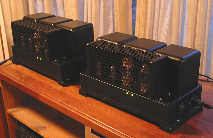
Picture 5.
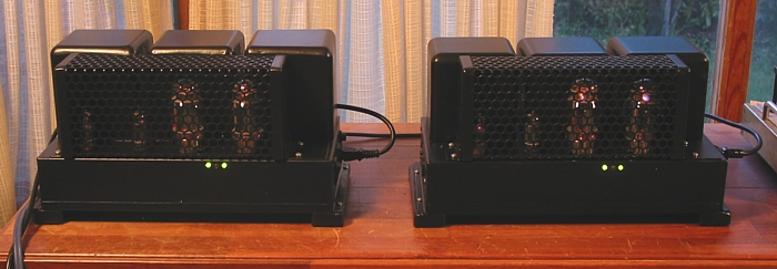
Picture 6.
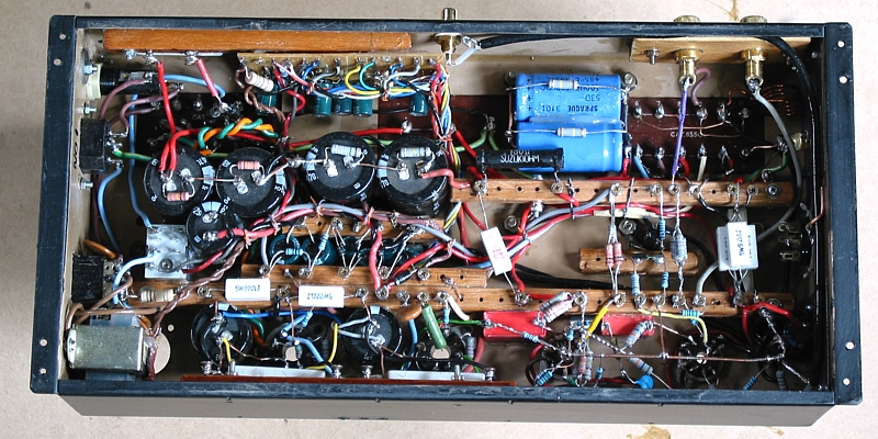
Picture 7.
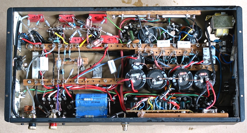
As a retired amp worker I don't do this kind of restoration work
for the ultra low prices I used to accept,
and I most surely will not do this sort of work ever again no
matter what price is offered.
A huge number of hours is needed to get this standard of
operation to meet modern expectations of
sound quality, reliability, and safety.
Another possible way to reform RCA amps, or build a whole new
amp :-
Fig 7.

If YOU spend 12 months training yourself to do this work and
while learning all you can from this website,
you too might be able to get old junk to perform better than
many brand-name amps now made.
Happy soldering.
To Re-engineered amps
To Index Page