TURNER AUDIO AM-FM TUNER
With tubed multiplex stereo decoder.
This page contains :-
Picture of the AM/FM tuner.
History of my tuner design, Schematics for FM input front end,
10.7MHz IF strip and ratio detector,
stereo multiplex decoder, AM tuner and audio detector,
power supply and full explanations of how it all works.
------------------------------------------------------------------------------------------
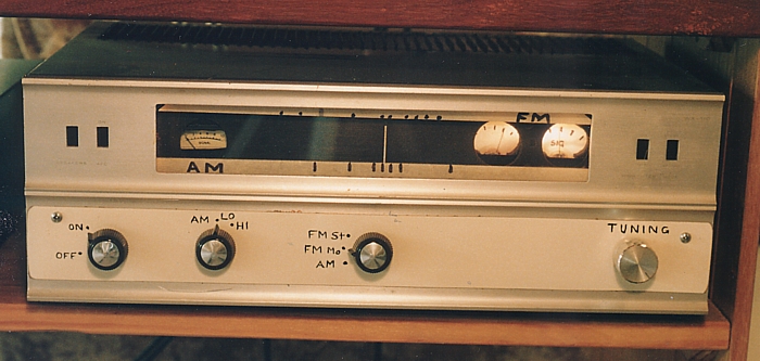
There is nothing fabulously good looking about this fully tubed
AM-FM tuner
which was once a very mediocre sample of a Trio tubed AM-FM
receiver with 5
watt SE channels from the late 1950s.
It is an experimental radio tuner and for my own use only so I
have not bothered
to have the front panel professionally re-created.
In the earlier edition of this website I had a page on the
multiplex stereo decoder
I had fitted within the above Trio AM-FM receiver which I had
heavily modified.
I bought the Trio cheaply for the purpose of being able to educate
myself about
tubed am/fm tuners and multiplex decoders.
What I learned immediately was how poorly the Trio RF and IF
stages worked
and how poorly the stereo decoder worked, and in general how
poorly the unit
was designed. In stereo FM the sound was like listening to to
music coming via
a long drain pipe. I couldn't figure what exactly what was wrong,
and I forced
myself to learn a lot. Einstein said things should be designed
simply as possible,
but no simpler.
Sure, Trio had done things too simply.
I spent many days reading the dusty and mouldy old books in the
Australian
National University basement archives where I found many
schematics and
servicing advice for late 1950s and early 1960s tubed FM receivers
in text
books from which some makers had based their circuitry upon.
In about 1999 I revised the IF design and ratio detector and I
replaced the
existing multiplex decoder with one shown on my earlier website
edition
but the stereo separation above 5kHz was poor due to the
unavoidable
phase shifts occurring in steep cut filters before the matrixing
to get
L & R output signals.
Late in 2005 I returned to my old receiver and removed all the
audio
amp circuitry to allow the receiver unit to become a dedicated
tuner with
some additional tubes in the multiplex decoder and to allow better
use of
the power supply.
The multiplex decoder is based on the principles used in the early
add-on
multiplex unit made for the early tubed Quad FM tuner. Quad's
early add-on
"MPX" unit used just 3 transistors and some diodes, and was not a
wonderful
performer, mainly because of the use of only 3 transistors.
But Quad knew what they were doing and they wanted to quickly do
something to satisfy demand for stereo FM.
But I can say my tuner is now a Turner Tuner, but based upon the
wisdom
of my father's generation.
I will happily compare it to a Leak Troughline tuner or any other
from Fisher,
Scott, Eico, etc.
The schematics of the whole tuner are below.
FM input stages,
This front end is about as simple as possible and yet there are
adequate features,
and is little different from an original Trio circuit from 1958.
I found the emission of one of the 6AQ8 of the original was low
and so I revised
the heaters to suit a 12AT7 which can replace the less common 6AQ8
without
other circuit changes.
The circuit has automatic frequency control which I leave
permanently connected
but you can still tune along the band OK with the stations popping
from one to
the next without to much drag from the AFC. The tuning stability
is so good that
once tuned, it stays on a station for days. Tuning methods are
explained below....
10.7MHz IF amps, limiter and ratio detector.
The IF amps and limiter are very conventional for the era.
The limiter works as a grossly overloaded single ended pentode
which is coupled
with tuned transformers.
The signals entering the V6 limiter grid do not have to be strong
to reach a
threshold level above which clipping occurs and any further grid
input signal
level will not produce much increase in output amplitude levels.
The signals applied
to V6 grid are many times the threshold for the beginning of
limiting during normal
operation.
The greater the antenna signal, the greater is the IF signal, and
so variations in
amplitude are rejected by the limiter and so are bursts of noise.
The frequency variations of the 10.7MHz signal remain well
preserved so
the audio and multiplex info remains intact despite the limiting
action.
Only variations in amplitude are limited and only the frequency
variations
are passed to the ratio detector which itself tends to be less
susceptible to
amplitude variations than Foster Seeley or some other types of
audio detectors
for FM radios. The grid current of the V5 6AU6 limiter produces a
negative voltage
across C8 which is applied back along R5,6,7 to previous stages to
lessen the
current draw of the 3 pentodes once a station is tuned. The tuner
seems to like a
high level of input signal from local stations to achieve really
low noise levels.
Two meters are used to indicate tuning.
Station tuning is correct when the signal strength meter needle
leans to the right
as much as possible. The zero volt meter is adjusted for 0V, the
centre needle
position, while tuning for maximum signal strength. The IF
transformers are
aligned to get maximum IF gain and limiting negative voltage using
a 10.7MHz test
oscillator. The ratio detector transformer is tuned to get maximal
audio output
signal at the lowest THD when the zero volt meter reads 0Vdc in
its centre position.
When tuning the station, the signal strength is indicated by the
signal strength
meter deriving a voltage from the cathode of V4 at R8 and V5.
As signal strength increases, negative grid bias is generated at
V5 6AU6 limiter
because of grid current charging of C8 due to V5 overloading and
the bias voltage
is used as an automatic gain controlling voltage, AGC, applied to
V3, V4 IF amps.
The signal at V4 cathode goes more negative when a station is
tuned so the
applied negative going voltage is applied across the signal meter
which has a
slight positive voltage applied to one side via R1/R2 divider from
the supply B+.
Once the station is tuned, the 0V signal derived from the ratio
detector
"centre point" between R15/R16 and is applied to the grid of
V1a. V2b is
the RF oscillator which oscillates at 10.7MHz below the FM station
frequencies.
The oscillator tank LC circuit is connected to the anode circuit
of V1a.
The dc applied signal at V1a grid varies its transconductance and
thus the
capacitance looking into the anode circuit of V1a becomes variable
according
to the applied dc grid voltage. The amount of capacitance
variation is quite
small in the region of a few pF, but at 100MHz 2pF has a large
effect on oscillator
tuning frequency, and the circuit is so arranged that if the ratio
detector develops
a dc offset voltage due to the IF frequency drifting away from
10.7MHz, since the
oscillator has drifted, then that dcV tends to cause a capacitance
change in
V1a which opposes such a change to the oscillator frequency, so
any effect of
drift due to temperature is reduced about tenfold and the set
remains well tuned.
Slight dcV offsets of +/- 1V are not enough to upset the linearity
of the composite
signal output from the ratio detector.
Without AFC there would be far greater dcV offsets and tuning
would indeed
not always stay where one sets it, and audible noise and
distortion is the result.
I was thinking of using a 6DT6 quadrature detector but there was
no need because
the ratio detector transformer in the original trio was quite OK.
The ratio detector diodes should be fast silicon signal diodes
such as IN918, etc.
Turner stereo multiplex decoder, 2005
The composite signal without any de-emphasis is amplified by V6
6DJ8 to raise
its level about 6 times. The low impedance signal from V6 cathode
follower is
applied to the two seriesed 19kHz bandpass LC filters via C6 to
extract the
19kHz and exclude all other F so it can be amplified by V7, 12AT7.
The tuning of seriesed bandpass filters L2/C4, and L3/C5
needs to be fairly
stable to make sure the phase does not vary at the output of the
19kHz amp
V7 anode. C4,5 were trimmed to get the phase of the 19kHz at V7
grid to
be exactly the same as at V6 cathode. I tuned the L2/C4 and L3/C5
by
using just the right paralleled values of polystyrene capacitors.
The amplified 19kHz pilot tone is applied to T1 and the full wave
rectifiers
1N4007 produce a 38kHz signal at R12, which is applied to V8 A
grid.
V8A&B, 6CG7, form a 38kHz oscillator which is synchronized or
locked
by the incoming 38khz signal at R12. The balanced output of tuned
T2 is
a clean 38 kHz sign wave. The tuning of T2 and T1 can make the
38kHz
signal have the correct phase relationship with the 38kHz
suppressed
carrier signal containing L - R AM modulation. The 38kHz
reconstructed
carrier signal must have the correct phase relationship to the
38kHz
suppressed carrier double sideband signal and this phase
relationship is
dependent on the tuning of the 19kHz bandpass filters of L2/C4,
L3/C5,
as well as the tuning of T1, and T2. T1 has one ferrite tuning
slug and and
T2 has two, and its a little difficult to describe exactly how I
got it all to align,
but it does, and it didn't vary much once adjusted when the tuner
is warmed up.
It is important to do alignment when such a tuner is well warmed
up so tuning
errors occur only when the tuner is cool, with some warmth then
helping the
alignment.
The double bandpass filters of L2/C4, L3/C5 are necessary to stop
harmonics
of lower frequencies from entering the V7 19kHz amplifier since
these
harmonics tend to make the 19kHz vary in amplitude and phase
dynamically,
which can then cause the 38kHz re-constructed carrier also vary
slightly in
amplitude and phase thus upsetting the fidelity of the recovered
stereo L and
R signals.
The transmitter may or may not have a notch filter to remove audio
artifacts
between say 18kHz and 20kHz before they add in a constant
amplitude
19kHz pilot tone.
But in observations of some signals on the band I found some
station's 19kHz
tone to appear to have some amplitude variations. if high level
second
harmonics of 9.5kHz audio tones occur, they can end up in the
19kHz amp
in the receiver.
(((( There is good reason that the 38kHz carrier component of the
38kHz
AM signal modulated with L-R audio is not simply included in the
composite
signal. It may have made detection audio of L-R much easier but
the overall
amplitude of the modulation signal used to modulate the frequency
of the
100MHz FM carrier would be too high, about 6dB greater. The system
allows
only +/- 75kHz variation in 100MHz carrier and it is the F
deviation which
determines the amplitude of recovered audio. If there was less
deviation
used for the L+R main signal the SNR would be worse and if
+/-150kHz of
deviation was allowed, bandwidth occupied by a station would be
doubled
so only 1/2 the stations would fit onto the 88 - 108 MHz band.
Because deviations allowed is +/-75kHz, we only need an IF
bandwidth of
300kHz to ensure there is minimal compression with a restricted IF
strip
bandwidth. When they dreamed up the Zenith-GE FM stereo
standards
in the late 50s, tubes were still king, and whatever was adopted
for the
stereo standard had to be not just possible but reliable using
tubes.
The system also allowed for additional sub-carriers to be added
into the
modulation composite signal but here in Australia we don't need to
have
filters to remove 67kHz or other carriers, although the higher
carriers are
used on some stations to carry a whole extra radio station's mono
signal.
One station I know which catered for horse racing broadcasts also
carried
the BBC News radio station which could be received using a special
filter
to retrieve the signal from the composite. A customer I had once
had me
build and install a kit to receive such signals and amazingly it
worked
very well. ))))
The cathode follower signal from V6 is also applied to the bridged
T notch
LC filter ( L1 ) tuned at 19kHz to reject the 19kHz pilot tone
which has an
amplitude of 10% of the maximum audio amplitude.
This is a band stop filter with a very high Q, and all audio L+R
signals
and the 38kHz double sideband signal with L-R modulation sidebands
is all allowed to pass and is applied to the T2 CT of the T2
secondary which
is floating.
The floating secondary is magnetically coupled to the T2 primary
so the the 38kHz oscillator signal is thus added to the total
composite signal
including suppressed carrier DSB signal, but not including the
19kHz pilot
tone. The signal at each end of the centre tapped T2 secondary has
oppositely
phased 38kHz signals. But the phase of the composite signal is the
same at
each end of T2 secondary. So you can draw the wave forms if you
are really keen.
The wave forms are simplest where you have just one channel that
is modulated.
I have drawn up all the wave forms and do know what is happening,
and rather
than spoon feed everyone, do try to draw the wave forms yourself.
Should you not do this exercise using a 10kHz audio sine wave tone
for one
channel then you may not ever understand the schematic I have
drawn and
you won't know how to build and get this schematic to work for
you, and you
won't get good stereo separation.
The output of T2 secondary is applied to each side of the diode
ring
demodulator. This is the part that hardly anyone understands but
currents
flow in alternate directions at a rate of 38kHz in R13&R14, or
R16&R15, and
the diodes control the direction of flow. At C16 and C17, the L
signal and R
signal is created due to the mixing of L-R audio modulation
amplitudes of the
38khz carrier and the L+R audio signals present. The audio waves
at C16
and C17 look like audio F sine waves but with a staircase 38kHz
wave
imposed upon them. This basically is switching noise. The C16 and
C17
audio signals are applied to the high impedance inputs of the
buffer cathode
follower V9A&B and the low impedance output signal from the
cathodes is
applied to a bandpass filter, see left channel, R26, C24, L4, C26.
This filter
removes the switching artefacts, ie, the 38kHz staircase waves.
The de-emphasis for the L&R channels is achieved with the
combined
effects of R17&C16, R18&C17 and the low pass filters. The
signal output
after the LPF is taken to a switch for selecting FM stereo, FM
mono, or AM mono.
The output from the switch is buffered with a second cathode
follower,
V13A&B, and the output taken to the outside world. The FM mono
signal is taken
from the V6 cathode follower after the 19kHz notch filter and
applied to the
de-emphasis and 35kHz bandstop filter before being taken to the
switch for
mono FM selection. This method of deriving the mono signal allows
the allows
mono signal to be independently gained without just summing
L&R signals after
they have been passed through the diode matrixing ring
demodulator, so the
distortion of the mono signal should always be less than the
stereo signal.
The sound quality does not change when switching from stereo FM to
mono
FM except that the the stereo signal gives good stereo imaging,
and so I
could say the THD is less than 2% at a high signal level. Perhaps
it is better
but there probably is some THD in my signal generator based on the
BA1404 chip which is not a best quality chip to produce a stereo
FM radio
signal. The sound is very listenable and compares very favourably
with more
recent FM tuners using all silicon chip based circuits.
Separation of channels is better than 35dB between 30Hz and 15kHz.
I tested with a signal gene which allows me to apply a different
audio sine
wave to each channel of the signal gene. The 96MHz FM stereo test
signal
is then received by an FM radio under test and the amount of each
audio
signal in each channel can be displayed on a dual trace
oscilloscope.
When one channel only has modulation, the amount of signal
"leaking" into
the other channel at -35dB compared to the channel with its
modulation as
the reference 0dB.
I was able to use the existing T2 38kHz transformer that was in
the old
Trio circuit. I wound the coils used for L1 and T1. L2,3, 4,5 were
small
inductors I had acquired; they worked, but anyone could wind such
inductors using some fine 0.1mm dia wire and a ferrite bobbin.
Every single capacitor and resistor has a critical value and
perhaps
several reasons why it has been chosen. C2,3 are used to tweak the
phase
response of the composite signal amp, V6, If the C2/3 are not the
right value
the separation will be poor.
There would be those who may be tempted to try a phase
locked loop for
synchronizing the 38kHz oscillator to the pilot tone. I have not
explored
this method, but it would be quire acceptable to use a chip for
this since
once the locking or synchronizing of the 38kHz oscillator carrier
signal is
achieved, there will be no difference to the audio.
AM tuner and audio detector.
The tube line up in this AM BROADCAST BAND for 500kHz to
1,700kHz front end is very common in many radios of the 1950s
except
for the features which make the audio performance a lot better
than most
old AM radios and tuners......
On the 6BE6 oscillator grid input, there is an unusual network of
C7&R2
and R1 is in series with the oscillator grid. This network is a
one of those
ceramic cap filters with CRC within, and common in Japanese
electronics or
that era. This was in the original Trio circuit which I think is
an attempt to
filter out the oscillator harmonic currents which could cause
interference with
pick up from short wave stations because if the harmonics of the
oscillator
currents and short wave stations have a difference in F of 455 kHz
then they
will be included in the IF signals and detected by the audio
detector.
On IFT1, there is a tertiary winding of about 10 turns placed over
the top of
a normal IFT primary. The wire is about 0.15mm dia, and well
insulated
from the B+ in the primary. When this coil is switched in
series with the
secondary, the IF bandwidth response is much widened, and in fact
becomes
slightly double peaked. This gives much wider and flat audio
bandwidth when
the two IFT responses are summed after the IF signal is amplified
by V11, 6BA6.
Tuning is supposed to be easiest with the IFT1 tertiary switched
out so that
there is a single peak in the IF response, but in fact the
original Trio IFTs do
give a slightly twin peaked IF response even when ever so
carefully aligned.
However, setting the tuning for between the two slight peaks is
easy.
Then the tertiary is switched in and the IF bandwidth is increased
from about
8kHz to 16kHz, thus permitting audio bandwidth increase from 4kHz
to 8kHz.
Tone control by the listener can boost the treble to about 10kHz
so not much
is lost from transmitted signals which contain up to 9kHz of audio
bandwidth
at least here in Australia. The tuning meter is not a Trio item
and a suitable
meter was set up as I needed to to measure the V11 dc current.
Virtually nobody else uses the cathode follower buffer, ( V12,
6AU6 ), after
the last IFT secondary. But not only does this CF isolate the
loading effects
of the diode detector from the secondary of the 6BA6, it provides
a low
impedance output to drive the 1N914 silicon diode detector. I have
found the
detector circuit as shown to give lower thd than a tube diode
detector.
The grid of the IFT2 sec is biased at +31V to give some idle
current in the
cathode R9 and to trickle a small current in the 1N914 diode via
R16&R17,
so that the non-linear turn on character of the diode is avoided,
since it is
always slightly turned on by the idle dc flow.
However, the AVC voltage is gained from C18 and 1N914 which are
powered
off the IFT2 sec because their loading effect is so slight. A
slight negative bias
is maintained on the AVC line, about -1.8V at the bottom of C16,
to stop too
much Ia flow in tubes when no AVC voltage is being generated when
the
tuner is left untuned to any station. with AVC applied.
The detector output is divided down by R16&R17 to give about a
volt rms of
output when a local station is tuned. Further slight boost of
treble signals
could be achieved with a small cap across R16 but I found it
unnecessary.
AM-FM
Tuner power supply.
This is a very simple power supply for a tubed tuner.
It has some zener diode shunt regulators for the input stages for
the
FM and the 38kHz oscillator stages to ensure tuning stability is
very good.
The original Trio power transformer was too small and ran too hot
so an
auxiliary power transformer was fitted to share the load when the
tuner was
a receiver with 4 other audio tubes. I have added small signal
tubes but
retained the two power transformers so the unit now runs fairly
cool.
There was no need to rectify the heaters to reduce hum; this was
tried,
but the very low hum levels on the AM and FM audio output signals
was
not reduced, and remained negligible.
To Index Page