SOME IDEAS FOR GREAT SOUND, 2012.
There may be some useful ideas about listening rooms, amplifier operation, and historical perspectives. Our pleasure
with hi-fi depends on many factors which I think I might identify. Some may easily be improved easily while others are
impossible to change.

I found many people don't care about the sound quality of music at home but others are fanatic about it and must
have technical standards for equipment and room which few can understand. I even found was common, but benign,
among many audiophiles to the point where the equipment mattered a lot more than the music the listened to, and
despite their keen interest in equipment it did not always lead to them having the the best sound possible, because
music is something subjectively judged, and tied up with any person's emotional disposition.
Regardless of my ideas about having a flat response and real hi-fi, I always put the wishes of my customers first,
and that meant giving them advice or equipment which pleased them but may not have pleased anyone else.

However, on many occasions I was able to make some improvements which were accepted by a few audiophiles.
There was often nothing I could do for a sound system or room because the room had no soft carpets or furniture,
and was highly reverberant, and their speakers required some time in my workshop to get them anywhere near
acceptable.

Using a pink noise generator, microphone and a response measuring box of tricks, I was sometimes able to change
the settings on their active crossovers feeding multi amp systems and get an inviting smooth response without 
aggressive HF, and with well balanced bass to make the music lush and delicious. This could take an hour or two.
But 2 months later, they had slowly altered the settings or changed an amp or speaker, and the music was back to
being terrible to me, but they seemed happy. Some liked almost no bass with high screechy treble, and in one
extreme case the guy liked only bass, with no signals sent to speakers above 300Hz.

So not all of us are within the middle ground of accepting conventional standards for the balance between bass,
mid-range and treble. I met many audiophiles who could never attend a live concert with an orchestra and with no
electronics at all. I always found the presence of an audience and performers to be a social activity, a connection to
others. To enable that to be pleasing, the concert hall must have acceptable acoustics. So the world evolved the
fine venues and many different instruments over centuries, and those who could afford it found some value for
music. Louis IV always had music at his Versailles palace, but the vast majority of others had only their folksongs
at occasional gatherings.

So what really matters?

THE LISTENING ROOM is most important, but houses with rectangular rooms and flat ceilings are notoriously
bad for listening to hi-fi because the 3 dimensions between parallel surfaces produce standing wave resonances
which alter the sound we hear. The room should have enough soft furnishings including deep carpets, wall hangings,
well padded furniture, bean bags, book cases and whatever else it takes to eliminate reverberations.

It is hard to change a room; you cannot buy one on Ebay. You may have to seek a builder, and suffer a divorce to get
a good room. The size of a room is not important, providing you sit near your speakers to not need high power and to
avoid the reflected sound from walls and ceilings. I have a room with irregular shape and with 30 degree sloping
ceilings to a ridge over the centre. There are carpets and furniture and junk, and it is it is 200 cubic metres with a
concrete floor. Everyone has said I have a fine listening room. But before it had carpets and furniture, it was horrible.

All the speakers I made or re-engineered were measured and the response tailored to give a flat response using my
room with microphones at 3 metres away from 2 speakers placed about 3 metres apart and facing the listening chair.
These speakers were found to be superior to most others anyone had tried, and they suited most rooms they had,
even when they moved to another house. I demonstrated my speakers in audio-visual retailing shops here, and to an
audio club in Sydney where they could not find any faults. I could never trust my own opinion because what my
customers thought was all important, but I managed please them all based on good application of scientific principles
that did not include any guesswork or wacky theories.

Your room should give naturally fine stereo imaging if the speakers have equal frequency F response and phase response.

In my tiny kitchen I have an old solid state FM tuner feeding a mono signal to the 5W audio amp in my Kitchen AM Radio.
I don't need stereo because the classical music I listen to transcends the importance of equipment and the kitchen
acoustics are just good enough. The point is that no matter how humble your dwelling, fine sound can be a part of your life.

SPEAKERS.
One good stereo amp plus one good pair of full range 3 way speakers is still the easiest way to get good sound.
My preferences for speaker design are listed at my loudspeaker directory.

There are some audiophiles who have assembled elaborate sound systems with separate amps for each speaker driver
which means having 6 amps for 2 channels, and perhaps another amp for a sub-woofer, ( something I think should not be
necessary. ) These tri-amp systems require an active crossover.
I have never met an audiophile who is fully happy which his system; that is part of being an audiophile. If you wish to join
the tortured legions of audiophiles, then just try to tri-amp. Such complexity is so difficult to get just right.

AMPLIFIERS. I prefer vacuum tubed amplifiers with plenty of class A operation. I didn't have to build many before people
began to tell me that they much preferred the sound from tube preamps and power amps. From 1995 I repaired many
solid state amps and would lend a tube amp to a customer while the repair was done. After finishing the repair, the
customer would not want to give me back the tube gear, and it was even a good sample of tube gear.
So later, they'd come back to buy something really good.

Amplifiers became cheap enough to be accepted by industry from about 1927 when movie sound brought ever large
audiences to movie thearters which could afford to lease or buy projection equipment. The general public could by
expensive radios, and the sound was not hi-fi, with bandwidth from 150Hz to 5kHz with lots of noise.
Noise of 78rpm records exceeded the distortions in triode amps with a 2A3 or 300B. But by 1950, the LP gave us
22Hz to 20kHz, and with very low noise. Mr D.T.N Williamson had established the principles of how to make an amp with
negligible noise and distortion and wide bandwidth. His famous 16W amp with a pair of KT66 in triode mode was a
sample of early hi-fi engineering which will be found to be quite superlative by many listeners some 66 years later in
2016.
Between 1950 and 2016, the huge experiments with change to solid state and then digital pulse-width modulated
amps have not made music more enjoyable. After 1950 it was always possible to get good amplifiers with enough
perseverance and money, and if you ignored about 90% of what was for sale.

In the 20 years after 1950, most speakers used very light weight cones with tight magnetic gap tolerances around
voice coils. These speakers were usually required only 1W to produce 95dB/W/M SPL between 500Hz and 2kHz.
With 2 such speakers, and for average LPL 85dB, you only needed 0.05W from each amp. For 105dB SPL, you need
5W, and 16W will give about 109dB, about the level when standing in the middle of an an orchestra of 50 all at full
effort. So a pair of 16W triode amps were fine. Most dome & cone dynamic speakers lacked good bass, and the F
response was anything but flat. Highly sensitive large diameter bass speakers from 1950s to 1980s had very bad
response problems and bass could be poor, and the cone resonances above 500Hz made all music muddled.
The speaker boxes were often highly resonant, hence the need to ignore so much for sale.
Neville Thiele and Richard Small guided manufacturers towards better bass. Intelligent speaker makers realized that
clear mid-range between 300Hz and 3kHz, you needed a smaller driver diameter of no more than 125mm and the
treble for above 3kHz could be from a dome only 25mm dia. The sensitivity of speakers dropped from 95dB/W/M
down to today's average around 88dB.

The lower sensitivity is due to heavier cones but the advantage was a flatter response. The response of drivers made
now can be far better than anything from 1950s. But you need about 5 times the amplifier power to reach the same
SPLs, so you will need 0.25W at each channel for average SPL of 85dB, with 25W needed for 105dB and 50W for 108dB.
This is plenty for most ppl so the use of  2 x 6550 or KT88 in UL or CFB mode will give the required levels.
See my 5050 I used to make. But some of my customers preferred my SE amps such as SE35 with 4 x paralleled EL34.
I found nobody could tolerate the levels when the amp levels were raised to where occasional clipping occurs with
rock and roll. I met customers whom had bought a solid state amps system to give 100W per channel, and who later
replaced all that with a tube preamp followed by a pair of 8W amps using one 300B.
And they suffered a financial loss when they found their little used second hand solid state amp was not able to be sold
for more than half the new price from a dealer. The triode amps they bought cost nearly as much as the SS, and
produced less than 1/10 of the power. But they found the music had life, warmth, and uncanny accuracy, despite
THD measurements being 10 times worse. I once was with 15 members of a Sydney audio club in 1996 where they
gathered in a listening room at a hi-fi shop. We first listened with a Gryphon power amp, 100W per channel of pure
class A solid state. Then the shop switched to two 20W SET amps using Allessa Vaic 300B tubes. It was like a light
turned on, and 14 fellows were in sonic heaven. The one whom wasn't happy owned a Gryphon, and I do not know
whether he kept what everyone else certainly did not want to own.

CONFUSED? If you are not technically minded, you will be bamboozled. Most music signals are a complex combination
of many "sine waves" occurring simultaneously. To know what a sine wave might be I suggest if you try studying
http://en.wikipedia.org/wiki/Sine_curve
If after 2 days you are still struggling to understand what a sine wave might be, and how many of them combine to form
a very irregular shaped wave form, you may have major difficulties with just about everything mentioned at this website.
But if you begin asking more questions, and searching for answers, then understanding becomes possible.
But the amp which has better measurements of performance may not be what gives the greatest musical delights.

The combination of countless sine waves at countless frequencies arriving at our ears are converted to digital nerve
signals and then interpreted by our brain as something written by Mozart, or by his great great great grate grandson,
Micheal Jagger.
When all the many frequencies in music are displayed on an oscilloscope, we see a line with an irregularly changing
shape up and down through a flat horizontal line which is the line for no signal, or the 0V reference line.
The shape of a very tiny portion of the musical wave is never a straight line. Amplifiers need to produce an output wave
which has the same shape as an input wave without any added shaping of their own, ie, distortions. Good analog amps
can simply re-produce the shape of an input wave to power a speaker.

So why is any amplifier needed?
The preamp signal or CD signal is often only 1.4Vrms, and only able to be applied to a high resistance load of above
10k0 and if a lower ohm load is used, the signal amplitude reduces and distortion is generated.
CD signal or preamp output called "line level" signals and the range of voltage swing may only be +/- 2Vpk, and maximum
current only +/- 3mApk.
Many CD players or preamps have output resistance = 600r, and if the output is short circuited, no harm is done because
there is say 2Vrms across 600r with max current = 3.3mArms. If a 8r0 speaker is connected, Vac is only 0.027Vrms, for
5.6mW, and the preamp cannot supply enough voltage or current to power a speaker which may need a maximum of
15.6Vrms and 3.9A for a 4r0 speaker, which is 61W. The power for speakers may be up to about 11,000 times the
power you might get from a preamp or CD player.

So the power amp puts AMPS into the voltage signal at speaker which has a shape the same as the preamp output,
except for a small amount of THD, IMD, phase shift and noise. If a sine wave sample of Vo from a power amp is
attenuated and overlaid on the preamp Vo, they may appear to be ONE wave on a dual trace oscilloscope.
The oscilliscope can be set to display the difference difference between the two wave shapes. If the waves are equal,
the difference signal is a straight flat line showing no difference exists.
But with a music or a pink noise signal you will always see a difference because the power amp will have some THD
+ IMD and noise and phase shift. The sine wave test can be done at between 500Hz and 2kHz where there is no phase
shift, and THD may be seen if it is over 1%. However, 1% THD is far too much so it is better to only use THD test gear
where a low THD signal is applied at input to preamp or power amp to determine their THD.
There are no short cuts to measuring amplifier behavior, and our ears are incapable of any sensible measurements.

For hi-fi, amps must be able to closely follow the shape of input wave forms and speed is important. Preamps should
have slightly wider bandwidth than power amps to make sure no additional loss of bandwidth occurs in a power amp.
We may expect a power amp to produce the maximum Po at clipping at 1kHz, and the same Po between 20Hz and
20kHz, using sine waves, with THD not exceeding +3dB above the 1kHz level. To do this properly, full Po between
14Hz and 50kHz should be possible, with THD increase less than +6dB.

Consider a single 6550 in triode or 300B in class A where output power = 9W into 2k9 so the anode Vac = 161Vrms
= 455Vpk-pk. At 50kHz, the time between a -peak and +peak = 20uS / 2 = 10uS. So the rise time = 10uS for
455V change, or 45.5V/uS. The rise time for a sine wave varies, and is an S shaped curve from a -Vpeak to +Vpeak.
At at the the middle of the rise at the zero crossing point the speed is a maximum of 64V/uS. If F is increased, the
amp may not be able to give a faster rise time, so the maximum output HF sine wave becomes a triangle wave with
high THD and lower pk-pk Vac.

A square wave test may demonstrate the amps rise time ability may not be more than 64V/uS at maximum Po.
impedance ratio ZR = ZR 2k9 : 5r6, then its turn ratio TR = 22.75 : 1, so Vo at speaker load 5r6 = 20Vpk-pk, and the
fastest V/uS for Vac change = 20Vpk-pk / 455Vpk-pk x 64uS = 2.8V / uS. The amplifier will be quite fast enough to
handle all F up to 20kHz where the rise time Vpk-pk with music will never be faster than 20V / 25uS, ie a slow 1.25V / uS,
The higher the Po, the higher the Vpk-pk, and for 100W to 5r6, Vac = 67Vpk-pk so for 20kHz, rise time = 67V / 25uS
= 2.7V / uS.
So the more powerful amps must be capable of higher speed, but at normal listening levels the total content between
5kHz and 20kHz may be 1/40 of the clipping level, and nearly all amplifiers can do this unless thay have a non flat
response at low levels.

5kHz square wave tests should not generate more than a few cycles of a ringing frequency above say 20kHz and the
rise or the fall time for say 9W for 5r6 load 20Vpk-pk may be say 3V / uS which indicates the amp would handle
frequencies much higher than 20kHz, if they were present and at low levels.

I have found many tube amps I made and some mass produced tube amps were able to process a 10kHz square
wave with less loss of HF content than many SS amps with BJT output devices. Mosfets have much better
bandwidth and are my preferred choice for solid state amps. With tube amps, the speed and accuracy depends
greatly on the OPT being a wide bandwidth device.

CD players read a digital data stream signal from a CD which is like fast moving Morse Code, dots and dashes,
1s and 0s. The voltage change of an analog sine wave music is contained in the data and a DA conversion circuit
produces an output voltage able to change once each 22uS, ie, 44,000 times a second, and there are great number
of voltage levels to choose from. The raw analog signal created by a DA converter looks like a stair case with irregular
step heights, but at regular horizontal distance between steps.

When this stepped signal is passed through a band-stop filter with high attenuation above 22kHz, the steps in the waves
are removed and you will see a wave which has the same shape as the signal recorded. To be able to describe a 20kHz
sine wave the sampling rate must be just over twice the 20kHz, and at 44kHz. Sampling rates of 96kHz are often used,
with higher number of step heights. The number of voltage information packets increase as signal F reduces.

It is possible to puchase a CD with 1kHz recorded to give THD = 0.001% , and each sine wave will be described by 44
points and if you draw a 1kHz sine wave with the digital information for 1kHz, and joined all the dots with straight lines
to make a kind of up-down stair case with 44 steps, and then fed it through a low pass filter with pole at 22kHz, you would
find the THD would not be more than the 0.001%, unless your DA converter was not up to par.
It seems like magic. And to those with no knowledge of how audio signals may be recorded as a series of numbers,
it is magic.
But we still need an amplifier to work a speaker and we can get superlative results with an analog input signals from a
CD player to feed an analog amp system. A "digital amp" can be fed data at its input and this is used to control the pulse
width of a HF square wave over 100kHz. The 100Hz wave conveys the analog information by varying the pulse width.
This is pulse width modulation, or PWM, and amps using PWM convert the HF signal to an analog signal at the amp
output which is fitted with a low pass filter to remove all the HF switching noise. Countless transistors in complex ICs
are used and circuitry is miniaturized to gain the speed required, and my knowledge of PWM extends no further than
I have explained. We now live in a world were 99% of all electronics is totally incomprehensible, and all circuits cannot
be serviced or repaired. If the "module X" does not work, we can only unplug it and plug in a new module X.

PWM amps are 95% efficient and produce little waste heat over their entire power range. There is far less need for
expensive weight and size of aluminium heatsinks. My first serious listen to a pair of Chi-Audio 100W amps within 150mm
cubes  taught me that all class AB amps made before 2005 had become irrelevant. So digital and PWM has liberated the
human race from the need to consume so much. But us humans cancel out all such gains because ppl spend hugely on
home theater amps with 8 x 100W channels for 3 pairs of left and right speakers plus a subwoofer and a front center
speaker. The power levels needed are no more than they were 30 years ago; we cannot tolerate higher sound levels.
100W or 12.5W per speaker would be quite OK. I do not think the quality of movie sound tracks warrants having such
an elaborate system. Having one good pair of speakers for stereo from movies or TV are fine. My Sony TV flat screen
TV has the most tiny stupid atrocious speakers, and I have not yet figured how to hook up an audio output to a hi-fi amp
and two good bookshelf speakers which are fine for 60Hz to 20kHz. These do not fart at me during some LF tones in
sound of movies etc, all due to tiny reflex chambers behind bass speakers only 50mm in dia.

Whether tubes sound better than all the silicon alternatives is something you may need to confirm. 

WHY ARE TUBE AMPS SO EXPENSIVE?
The main problem, apart from greedy manufacturers using slave labour in Asia while selling the product at 10 times the
cost of mass production is that relative demand is low, and the weight and size is much higher per Watt of audio power
than for any AB SS amp let alone a PWM amp. To make low numbers of tube amps in contries where wages are 10 times
higher than China or other asian countries means the labor and material costs are always going to be very high per Watt.

But depite the high cost per Watt for tubed audio amps, I found there were people who were prepared to pay for something
handcrafted which sounded better.
I often was able to re-engineer some asian made garbage or older US or UK amps bought on Ebay to get the performance
higher. The standard of workmanship in much for tube gear for sale now is entirely superficial and the slick marketing
advertizing online is mostly BS.

WHY ARE HEAVY TRANSFORMERS NEEDED ?
Tube amps have a high amount of class operation so the power transformer works hard even with no sound.
For an amp with 4 x 6550 tubes making 2 x 60W class AB1 for 2 channels, the power supply must provide up to 240W for
anodes and a total of 55W to heat all the cathodes. The PT should be rated for 400W to avoid it getting too hot.
Each output transformer capable of 60W must be about same size as a 120W power transformer to get low heating and
low THD at LF. So expect a good 2 x 60W amp to weigh 25Kg.

WHAT ON EARTH IS CLASS A OR AB?
For the non technical person reading this audio-ideas page, I can only explain if you can imagine "blokes sawing logs."
Consider one single man sawing through a log with a long bush saw. His motion of the saw is slightly different in each
direction and if a graph was drawn the wave form would be a sine wave with maybe 14% THD, mainly 2H.
And so it is with a single single tube, or a number of them in parallel. The main distortion artifacts are even numbered,
2H, 4H and so on which affect the music fidelity.

When another man joins the other cutting a log so that each man holds each end of the saw, the motion to and fro
becomes more even in each direction, and the even numbered H products reduce while there are odd numbered 3H,
5H, 7H at levels below that for one man.

This describes one man working in like one tube in Single Ended ( SE ) mode, or two men working in push-pull ( PP )
mode, and in both cases each man contributes equally to sawing the log, and for all of the saw motion to and fro,
so power is called Class A. Before solid state amps replaced most tube amps by 1970, many tube amps had output
tubes working in pure class A where an SE single tube of a PP pair generated Ia change for the whole wave cycle.

Class AB amps are like having two men sawing a log, but during each wave cycle each man lets go of his end of the
saw for nearly 1/2 the wave cycle so most of the sawing power is done by one man then the other, on each 1/2 wave
cycle. Class AB sawing methods were deeply resented by members of the Logcutters Union, because it was much
harder to do. But the bosses tried to cut wages down because each man was working for only part of the time.
But vacuum tubes, transistors, mosfets can more easily turn on and off than men, and they don't mind working
harder for each 1/2 wave cycle. This is class AB where devices switch off for up to 1/2 the wave cycle. More
odd numbered H are produced than for pure class A, but the devices do not need such a high idle current so the
devices run cooler and last longer but can make maybe twice the maximum Po if compared to where they work
to make only pure class A Po.

It is a technically valid argument to insist that class A Push Pull reduces THD to a minimum without trying to be fanatic.
But for 2 x EL34 pentodes in pure class A the THD at max Po of say 22W, THD = 3% and be mainly 3%, and the
amp output resistance is well above the speaker load ohms so there MUST be about 20dB NFB to reduce the Rout
to about 1/10 of speaker ohms so that for any equal amplitude of different F input Vac gives a nearly constant Vac
level at the output, where the speaker load ohms may vary between say 4r0 and 24r0.
The 20dB NFB will reduce THD max from 3% near clipping to 0.3%, and at 1W, expect 0.1%.
In 1947, Mr D.T.N Williamson used 2 x KT66 connected in triode mode to make 16W at 0.1% THD, pure class A,
with 20dB NFB. All forms of recorded music sources were on discs which included 10 times the THD of the power amp.
This changed in following years with vinyl discs and other sources and people still are arguing whether vinyl stil sounds
better than the latest digital source.
But regardless of the source, a well made Williamson type of amp will sound excellent in 2017 when used sensibly
with speakers of medium sensitivity.

Th world has turned away from tubed analog amps to solid state PWM amps which cost less per Watt, and there can be
4 amps in a box for home theater which consume 1/10 of the power of one 16W tube amp channel.
So the revolution to digital uses less mains power and CO2 produced per listener has declined, so don't worry if 0.01%
of listeners insist on vacuum tubes; the global greenhouse effect is occurring because seven billion ppl want more and
more, and when they get it they will just want more, which takes them to a standard of living where they'll only want more.

Unfortunately, many of the 7 billion hate paying power bills and they will not grant funds to increase alternative energy
sources like solar. Everyone blames everyone else for non-sustainability. After I die soon wars will be fought over
issues relating to having too many ppl on thre one planet. Please don't blame ppl who like triode amps, and refuse to
buy vast amounts of junk which generate ever bigger amounts of CO2.

If you are thinking about buying tube amps, borrow something for a week before making any decision. If there is an audio
club within 100km, attend a few meetings and get to know what to expect.

To quote figures for tubes, here are some very basic considerations :-
Table 1. Possible tube choices for amplifiers.
Tube types,
all class A
SE Triodes SE Beam Tetrodes
or Pentodes
PP Triodes PP Beam Tetrodes
or Pentodes
THD max PO
Zero NFB
5%, mainly 2H,
minor 3H
13% variable
2H and 3H etc.
2% 3H,
other H low
possible 2% many H
NFB needed
for THD%
12dB GNFB
for 1.25%
 
20dB GNFB for 1.3%
or use UL or CFB,
then 10dB  GNFB,
maybe 0.4%  
12dB GNFB,
get 0.5%

Need 20dB GNFB
or use UL or CFB,
then 10dB  gnfb maybe 0.3%
Tubes for 8W
pure class A, for
96dB+ speakers.
1 x 300B,
2 x 2A3,
1 x EL34T,
1 x 6550T,KT88T
1 x EL34,6550,KT88,KT120
2 x EL84,6V6, SEUL, CFB.
2 x300B,2A3,KT66T
4 x EL84T.
2 x EL84, 6V6
UL or CFB
Tubes for 16W
pure class A, for
93dB+ speakers.
2 x KT88T,6550T,KT90T
2 x 300B,
4 x 2A3,

1 x 845, 211
2 x EL34, KT66, 6550, KT88,
KT90, KT120, SEUL, CFB
2 x 300B, 4 x 2A3,
2 x 6550T,KT88T, KT90T, KT120T,
2 x 6550,KT88,KT90,KT120
UL, CFB
Tubes for 32W
class A or AB, for 90dB+ speakers.
4 x 300B,6550T,KT88T,
KT90T,KT120T
2 x 845, 211
4 x EL34,KT66,6L6GC,
5881,6CA7,6550,KT88
SEUL, CFB
2 x 300B,845,211 6550T,KT88T,KT90T
KT120
2 x EL34,6L6GC,KT66
KT88,KT90,KT120
Tubes for
48W+, class A or AB
6 x 300B,6550T,KT88T,
KT90T,KT120T
2 x 845, 211
4 x 6550,KT88,KT90,
KT120,KT150
SEUL, CFB
4 x 300B 6550T,KT88T,KT90T
KT120
2 x 845,211
4 x EL34,6L6GC,KT66
2 x KT88,KT90,KT120,
KT150
Expense per W. Highest. High  
Low Lowest
Sound quality.  
Can be best. Worst unless CFB, UL +
GNFB, then can be best.
Can be best. Fair unless CFB, UL +
GNFB, then can be best.
Table 1 shows that if someone has horn loaded Lowther or Klipsch speakers with sensitivity >100dB/W/M then 4W amps
with 1 x 2A3 per channel will be OK.

For speaker sensitivity >96dB, 8W is OK. For >93dB, 16W is OK. For >90dB, 32W is OK, and for >87dB, 64W is OK. 

The cost per Watt for low power class A amps is high, but there are not many Watts.

For 20W SET class A or 50W PP with 845, cost per W is very high due to low production numbers and the extra
work in PSU and OPT.

The trouble with 8W low Po amps with large sensitive speakers is that when speakers are replaced, smaller insensitive speakers
are often chosen, so that 8W amps are unable to give good sound. So the listener must settle for lower volume levels.

What amplifier power is needed?
Table 2.
SPL produced
2 speakers at 
3M in average room
Power for
SPL both amps.
Speaker spec = 87dB/W/M
Power for
SPL both amps.
Speaker spec = 90dB/W/M
Power for
SPL both amps.
Speaker spec = 93dB/W/M

108dB
256W
128W
64W
<105dB
128W
64W
32W
102dB
64W
32W
16W
99dB
32W
16W
8W
96dB
16W
8W 4W
93dB
8W
4W
2W
90dB
4W
2W
1W
87dB
2W
1W
0.5W
84dB
1W
0.5W 0.25W
81dB
0.5
0.25W
0.125W
78dB
0.25W
0.125W
0.062W
75dB
0.125W
0.062W
0.031W
Table 2 is a conservative guide for selection of amplifier power based on a manufacturers speaker specification for sensitivity.
If you test a speaker in an anechoic chamber, all the sound is from the speaker and not reflected from walls, floors and
ceilings as it happens in rooms of houses. If you are in the anechoic chamber during tests, it will seem you have to use
higher volume levels to get the same level of sound heard in normal room.

Similarly, if you test a speaker in the middle of a grassy field, there is very little reflected sound. For outside venues a public
address system has to work harder than for an inside venue.

If a speaker has specified sensitivity = 87dB/1W/M in an anechoic chamber, it will make 90dB/W/M in an average room,
but where the distance is increased to 3M, expect 84dB. Use of 2 speakers means the power is 0.5W in each.

My table shows that for speaker rated for 87dB/W/M, you would need 1W average to make 84dB SPL in an average room,
which means each amp makes 0.5W. Each increase of 10dB SPL requires 10 times more amp power; 94dB needs 10W,
104dB needs 100W, and 107dB needs 200W. The power doubles for each +3dB increase of SPL.

Therefore 2 x 100W amps are needed for 107dB.
However, I don't know anyone who likes music that loud anywhere, and 2 x 50W amps are plenty. If someone stands near
us to sing a song, or sits at a piano, or plays a violin, or guitar, we mostly do not need a hi-fi system to make it sound any louder
from a recording. But you cannot say this to someone addicted to high levels of Heavy Metal, and who does not care about
damaging their ears.

Many speaker manufacturers confuse buyers because their speakers are less sensitive than customers expect to buy, so that
SPL levels are quoted for where Vac applied = 2.83Vrms. This makes 1W for 8r0 speakers, but if speakers are 4r0, then
2W is made, and the 4r0 speaker may be 1/2 the sensitivity and need twice the amp power.
So, just be aware that where lies can be told, and truth obscured, it will be, and unless you are an expert, you will be conned.
Sellers of all things want your money, and they will tell you bullshit to get it.

MY SIMPLEST RECOMMENDATIONS :-
(1) Buy a pair of floor standing speakers with 3 way drivers similar or equal to what I have built.
The sensitivity of many modern speakers is often between 86 to 89dB/W/M.
(2) Buy a pair of monobloc tube amps giving at least 32W each. Most ppl find that enough, unless they are under 30,
and like to have loud pop music outside, and then 2 x 100W is needed.
(3) Position the speakers 3M apart, 1M off walls, and 3M from a seat. You should be able to point both speakers at the
seat, but treble may seem too high, so point axis to cross behind your seat.
99% of all the people I have dealt with since 1995 will find this recipe to be correct.

You could easily spend $10,000, and many don't have that sort of dough for audio gear so try in vain to find a $1,000 solution.
Wives often control 99% of all domestic transactions. I know why my earnings were so low, and why there were so few who
contracted me to build a total amplifier + speaker combination, Less than 3 in 17 years. But a larger number bought my amplifiers
with 30W to 100W capability to drive speakers with sensitivity 88dB to 92dB.

NEGATIVE FEEDBACK.
The high amount of distortion without any negative feedback, ( NFB ) in tube and solid state amps is much reduced by a simple
technique of corrective circuitry known as a "negative feedback loop", or "negative feedback network".
This circuit technique has been used since about 1925 with early vacuum tube amps to make the amps much more linear
than they were without NFB. It was not always regarded as being simple back in 1925, because hardly anyone knew how to stop
unwanted oscillations when any NFB was applied, and they didn't like having to use an extra input tube on the amp.
But by 1950, costs of all parts including tubes were lower, and most accepted the better performance of amps with NFB and
which were designed by more knowledgable people.

NFB works on a simple principle. Say your wife tells you to mow the lawns and help with housework and you just don't, then
expect domestic happiness to suffer. This is life with high distortion. If the wife's NFB signal was applied to your mind, and accepted
by your mind, and you do mow the lawns and help around the house, then there are less rows and more sex and life has low distortion. 

Without NFB, an SE triode amp makes a typical 5%  THD.  If the signal applied to grid contained 4% of THD which is the
opposite phase of the THD at anode, then the triode would amplify that to produce a signal at anode which opposes the
production of the THD, so THD may be reduced to 1.25%, and this much THD reduction is a factor = 0.25, and is -12dB.
So 12dB of applied NFB can reduce THD by roughly 1/4.

In the past, manufacturers competed with each other by offering amps with ever lower THD, and even D.T.N Williamson
offered a triode amp with 0.1% THD at 16W. Very few makers could reduce THD further unless they made very good
wide bandwidth OPTs and they understood critical damping networks to tailor open loop gain to prevent oscillations
at below 20Hz and above 20kHz. When solid state came along, there was no OPT, and by about 1993, Halcro of
South Australia made 200W mono amps for class AB mosfets which produced 0.0001% THD at all F below 20kHz,
and at 200W.

This was outstanding solid state engineering. The amps even had switch mode PSUs. I do not know if they have ceased
production, because I now seldom hear anyone mention them. I suspect many who paid their high price may have found that
0.0001% THD did not improve sound more than having 0.1% THD, so THD could be 1,000 times worse than Halcro before
anyone can hear any difference at the 1W level.
But in about 2000, I read where the Hong Kong audio club tried a pair of Halcros, and wrote "Halcro like 300B, but go louder."
This meant the 300B was the gold standard for the HK club, they didn't say Halcro was better, and they insulted Halcro by
saying their "cutting edge" SS amp was like a 300B tube amp where there could not have been a bigger difference.
Halcro went on to sell many pairs of amps for $50,000 a pair, but maybe none to HK audio club members.
I did know one Sydney audio club guy bought a pair. He was a top heart surgeon used to earning $3,000 an hour, so it took
a few days to pay for such amps. Nobody needs to spend such vast sums of money.

But the reduction of THD, IMD, and phase errors and amplitude errors or any other amplifier artifacts can be much reduced
by NFB, and if done correctly, it works wonders to make tubes sound better than if no NFB was used.

Fig 1. Basic function of GNFB loop in typical tube powe amp.
NFB-basic-loops-8585.GIF
The diagram explains how a fraction of the output voltage containing distortion is fed back to the cathode of V1, one of the
two live input terminals of the tube amp. The difference between the fed back signal and grid input signal is amplified to
make the output signal. This difference signal contains a sample of the distortion at the output. It to is amplified to cancel
its own production. The amount of distortion reduction is easily calculated by the formulas in the lower right side note.

For those still confused about relative phases of signals within amps, the + or - sign before Vrms indicates the relative
phase of the signal voltage, and there is 180 degrees difference between + and - phases. The two phases are like two
kids on a see saw, and while one ascends, the other descends, much to their merriment.

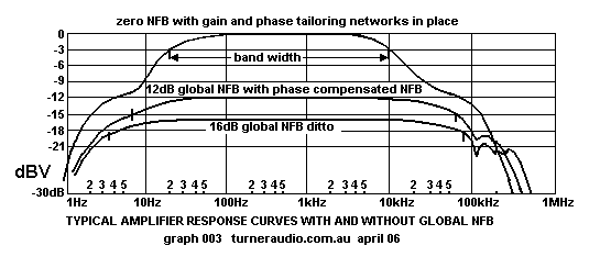
Fig 2. F response of typical power amp without and with GNFB, with gain shelving R+C networks for stability with NFB.
graph-typical-response-amp3.gif
The response here with only 16dB shows no peaks in response with GNFB and pure R load, and will remain stable without
oscillations at LF and HF with no load connected. It should give slight peaked response at HF with only 0.22uF load,
but should not oscillate.

LF and HF oscillations may go unnoticed, and cause tube failure and damage to parts.

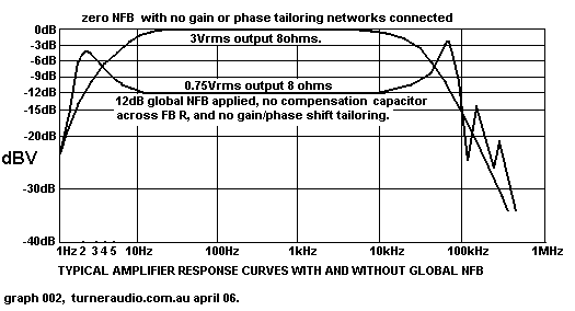
Fig 3. F response of typical power amp without and with GNFB, without gain shelving R+C networks for stability with NFB.
graph-typical-response-amp2.gif
Notice how Fig 3 shows peaked response at 2Hz and 75kHz which shows the amp is very likely to oscillate at LF and HF
without a load connected, and with pure C load of say 0.22uF. This was the typical poor response of badly designed amps
from 1950s. 
Back to Index