BASIC
TUBES 4A
Content :-
General discussion, formula for UL µ.
Fig 1. Graph for reduction of beam tetrode Ra vs Vg2
applied from OPT taps.
Fig 2.Current generator model for 50% SEUL with 6550.
Fig 3.Current generator model for 40% SEUL with 6550.
Fig 4. Current generator model for 20% SEUL with 20% CFB
with 6550.
Fig 5. Current generator model for 20% SE CFB with 6550.
Many notes between each figure.v
Ultralinear Ra, µ and gm.
NOTE. Where the screen of a beam tetrode or pentode is connected
to a tap on OPT primary between
the B+ and anode connections, the tube is said to be configured
in "Ultralinear", or UL.
The real world operation is marginally more linear than pure
tetrode or pentode and at low Po levels
is just as linear as triodes. The term "Ultra" is a silly term
from 1950s because the marketeers of tubed
hi-fi amps in the 1950s had the same present day tendency to
speak and write the language of 'Jargonese'
where ppl are lulled into believing some imagined bullshit.
Almost everyone could not understand anything an engineer
said, so they needed to be kept away
from customers. Engineers maximized the costs of the design
process because they always tried to make
audio gear heavier and more expensive than the opposition
company who employed Glorified Amateur who
had married the daughter of the CEO who smiled whenever he heard
a customer say "Oh gee, that sounds good",
because he knew about the missing quality.
No buyers really knew what linearity was, or what "ultralinear"
could mean. But ever since anyone formed a
company to to sell anything, those at the top soon realized they
needed to treat customers like mushrooms, ie,
keep them in the dark and feed 'em bullshit. Our whole world
continues to be based on the robust principle of
trying to sell something for more than its worth.
The marketing employees were totally useless with a soldering
iron or getting hands dirty in a factory,
but could make a $1,000 suit look good, while smiling, and
fertilizing the growth of sales of their amps with
sprays of incomprehensible bullshit. There have never been any
regulatory laws to outlaw bullshitting because
applications of any such law would lead to an exponential
increase in bullshit, with countless blokes in suits all
uselessly arguing in courts forever at huge expense, and your
goods and services would cost more because
you'd have to pay for the suity blah-blah.
We were lucky not to have someone invent "Hyperlinear",
but Quad did invent the idea of "wire with gain".
Strange, that was, because the wire had gaps where a vacuum
existed, and later, bits of semi-conducting
Silly Con:-)
The "UL connection" for a beam-tetrode or pentode is the
use of taps on a primary anode winding of OPT
to feed a fraction of the anode Vac to the screen, instead of
having the screen connected to a fixed B+.
Ultralinear works to allow a substantial fraction of the
internal NFB which occurs in a real triode so that
the harmonic distortion of a pure beam tetrode or pentode become
similar to those of a triode, and the very
high Ra of tetrode or pentode is greatly reduced. The UL
connection allows the Va to swing negative
almost as much as for pure tetrode or pentode, so UL connected
tubes offer nearly the same Po at
pure tetrode or pentode, which is usually twice the triode Po.
UL can give less THD than a triode for the same Po.
The use of 43% UL taps was very common. RCA usd 30%, and Leak
used 50%. With 43% UL taps,
the typical damping factor = 1, and with a moderate 15dB of
global NFB the DF could be 10.
Plenty of makers tried to use 26dB GNFB for DF > 15, and THD
= 0.07% at 40W. There were THD wars,
where makers competed by marketing amps with ever lower THD, but
I know that was bullshit because with
26dB GNFB, any UL tube amp had a small margin or stability, and
it won't sound better than 15dB GNFB.
In most domestic listening situations, a 40W amp seldom
exceeds average levels = 1W, and if THD
is 0.25% at 40W, then at average levels it is 0.04%. 1W to 8r0
speaker = 2.83Vrms, and if THD = 0.04%,
then Vd = 1.1mVrms. The IMD % is always about 3 x THD, and is
anyone going to hear 3.3mV of harmonic
garbage even if it powers the speaker on its own? Tests in 1950s
mentioned in RDH4 showed 0.5% THD
is barely perceptible by those with the keenest hearing. So
99.99% of the public will not suffer if THD
= 0.04%.
Halcro of South Australia managed to get THD down to 0.0001% at
200W and at all F below 20kHz, a remarkable
achievement with solid state combined with huge amounts of NFB.
No schematics have ever become available,
and I think the company no longer exists.
But in about 1997 the Hong Kong Hi-Fi club compared performance
ot a pair of 200W Halcros with a pair of
8W amps with a lone 300B, and concluded, "Halcro is like 300B,
but just goes louder." That they could be alike,
or could even be compared implies the HK folks were quite happy
with 8W from a 300B, and they were not
going to fork out $50,000 ( the price in 2000 ) for a pair of
Halcros.
The UL tap position is often quoted in OPT specifications
as the percentage of primary winding turns between
B+ and anode. A common figure was 43%, recommended by Mullard
for EL34 and EL84, and it suited many
designs of OPTs which had 7 layers of primary wire each side of
the CT. The UL tap for the screen was brought
out at 3 layers away from CT on each 1/2 primary, so the UL
fraction = 3 / 7, 42.85%.
In 1960, A typical UL winding pattern of P&S interleaving 4P
- S - 3P - CT - 3P - S - 4P. Thus there were 3
primary sections interleaved with 2 secondary sections. This
gave rather high leakage inductance and amps
were difficult to stabilize with GNFB ( due to engineer
ignorance ) and the OPT design was a dumbed down
version of applied principles outlined in 1947 where Mr
D.T.N.Williamson had invented the wide bandwidth
OPT described in Radiotron Designer's Handbook, 4th Ed, 1955,
page 748. Its online if you Google.
Willy's 16W OPT had 5 primary sections each with 5 layers, and 4
secondary sections each with 2 layers
for each of two identical bobbins placed side by side on a non
wasteless pattern GOSS E&I core where
the window was relatively large at 75mm x 25mm. His design used
twice the weight and 3 times the labour of
what manufacturers were prepared to sell in amps to the public
in 1960.
Leak amps had 50% UL taps, which meant the OPT had the
same 3P x 2S interleaving, with
4P - S - 8P - S - 4P. This meant the primary CT was at one end
of the 8P center section and at one end
of the two 4P sections in series. HF performance was poor and
the Leaks I serviced were hard to stabilize.
But one early version of a Leak monobloc with 2 x KT66 did have
much better OPTs with more sec sections
for better HF. Those early Leaks had Williamson's ideas, and
were very good. But as demand and competition
increased, Leak must have decided to reduce quality to reduce
their construction costs like everyone else
and lower the price to get better sales.
I found that UL% somewhere between 33% and 66% is OK for nearly
all tetrodes and pentodes, with the 66%
being best for where at least 1/2 maximum AB1 Po is pure class
AB Po, ie, RLa-a is quite high compared to
most factory made amps. Once you increase UL% beyond 66%, ie,
move the UL tap closer to anode, the Va
swing becomes limited by the Ra curve for Eg1 = 0V as occurs in
triode mode where AB1 Po max can only
ever be about 1/2 the Po for pure tetrode or pentode.
I found that Single Ended UL class A operation with a 13E1 with
66% UL tap gave 28W which is a lot more
than the 16W possible in triode mode.
The UL% needs to be converted to a FRACTION for use in
equations.
Equations for UL gain were worked out in 1955 but may
have been somewhat
inaccurate. They relied on knowing Ra for tetrode, gm for
tetrode or triode ( same ),
and µ for triode.
Ultralinear UL µ may be calculated :-
UL µ = µBT / [ ( UL Fraction x { µBT - µT } / µT ) +1 ]
where µBT is beam tetrode amplification factor or Gm g1 x
Ra,
UL fraction is the Pri CT to screen tap turns / Pri CT to anode
turns,
µT is triode amplification factor or ( 1 / Gm g2 ) // Beam
tetrode Ra.
1 is a constant.
Using previous results, uBT = 180, µT = 6.36.
The formula should work for UL Fraction = 0% where g2 is taken
to fixed Eg2 +Vdc, ie, operation
is pure beam tetrode or pentode with g2 bypassed to k.
It should also work for UL fraction 100% where g2 is taken to
anode, ie, it is triode operation.
For UL Fraction = 0.0, ie, g2 connected to B+ for pure
beam tetrode,
ULµ = 180 / [ ( 0.0 x { 180 - 6.36 } / 6.36 ) + 1 ] = 180 =
µBT.
For UL Fraction = 1.0, ie, g2 connected to anode for
triode,
ULµ = 180 / [ ( 1.0 x { 180 - 6.36 } / 6.36 ) + 1 ] = 180 / [ (
27.3 ) + 1 ] = 6.36 = µT.
Now try for 50% UL, UL Fraction = 0.5.
UL µ = 180 / [ ( 0.5 x { 180 - 6.36 } / 6.36 ) + 1 ] = 180 / [
13.65 +1 ] = 14.938 = 12.29
The g1 gm is same for all modes of operation so UL Ra
= UL µ / g1 gm = 12.29 / 0.0055 = 2,234,
say 2k2 approx.
Fig 1. UL reduction of Ra.
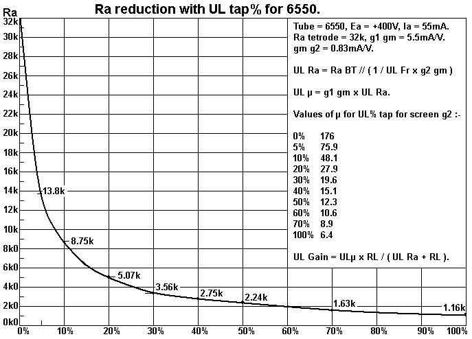
Fig 3 shows how even a UL tap of 10% reduces Ra from 32k to 8k8.
A number of manufacturers used only
20% but when you analyze the THD reduction it is not as good as
having say 40%, where Ra is reduced by
more than 1/10 at 2.k7. The significance of UL taps between 40%
and 50% is that max Po for any class AB
load is almost the same as for pure beam tetrode.
For Ea = +400V x Ia 55mA, RLa-a = 8k0, gives first 12.1W in pure
class A with 30W AB1. But with RLa-a = 4k0,
you get 45W AB1, but only 6W for initial class A. However, best
RLa-a is about 10k0 with the first 15W in class
A and 28W max in class AB1. With UL taps at 50%, the Ra-a = 2 x
2k2 = 4k4, and without any GNFB the damping
factor = 10k0 / 4k4 = 2.2. This is easily increased to 10 with
about 14dB Global NFB and and the music will stun
many listeners.
-----------------------------------------------------------------------------------------------------------------
Fig 2.Current Generator model, SE 6550 :-
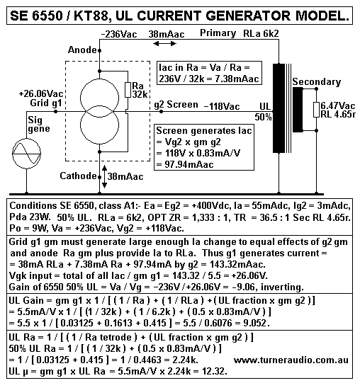
Fig 2 shows beam tetrode set up with anode load of 6k2 at the
primary input to an OPT with
secondary load of 4.65r. This diagram replaces an earlier rather
untidy model which showed TWO parallel
current generators, one for g1, other for g2.
In fact, the 6550 only has ONE electron flow, and we can still
consider the tube as a Voltage controlled
current source, but with TWO grids sitting in the electron
stream which both have an effect on the ONE
stream of electrons to anode.
The symbol of two intersecting circles is universally
recognized as a constant current source with infinite
resistance from top to bottom. The horizontal lines drawn in
from one side or other represent high high
resistance inputs to allow an applied voltage to change the
current flow according to a defined amount of
transconductance, gm, in mA/V. Where the voltage at either input
terminal remains unchanged, there is
no change to the specified current which remains constant.
In the real world, the 6550 like all other tubes and
devices has a finite resistance from top to bottom,
known here as the Ra of the tube under the conditions of
operation. The anode does have a
transconductance effect on Ia, and with fixed Eg2 and Eg1, we
would find anode gm = 0.03125mA/V.
It is always present, even where Vac is applied to g1 and g2, so
we can depict the anode gm as a
resistance Ra = 1 / gm = 1 / 0.03125 = 32k.
Fig 2 shows the 6550 set up for SEUL with 50% screen tap.
This has the effect of lowering the Ra to 2.24k,
making the 6550 perform similarly to triode mode with lower THD
than pure beam tetrode, a good damping
factor of 2.7. In UL or beam tetrode, max Po = 10W into 6k2. Max
Po in triode = 7W into RLa = 4k8 for the
same Ea and Ia idle conditions. I show the Po with 9W, below the
clipping level.
The effect of THD and transformer winding losses are not
included.
In Fig 2, screen g2 produces a current = Vg2 x gm g2 but
we would never find it if we searched for it.
What is really happening is that g2 has a combined action with
grid g1 to produce a RESULTANT
electrostatic field change which works on Ia.
A negative going Vg2 = -118V tries to reduce Ia
by - 97.94mA, while positive going Vg1 = +26.06V tries
to increase Ia by +143.33mA, and the resultant Ia = +143.33mA -
97.94mA = +45.39mA. +7.38mA flows in Ra,
and +38.0mA flows in the load. The + / - signs indicate
directions of V and I.
The 50% UL output resistance could be tested without
having any Vac present, and simply forcing Va
to move -10V. The screen g2 would have -5V applied which then
generates Ia change = Vg2 x gm g2 =
5 x 0.83 = 4.15mA.
There is also current flow in Ra = Va / Ra = 10V / 32k =
0.3125mA.
Total Ia change for forced Va change = 4.4625mA, thus Rout = 10V
/ 4.4625mA = 2.2k.
The beam tetrode g1 gain A = µ bt x RL / ( RL + Ra bt ) =
176 x 6.2k / ( 6.2k + 32k ) = 28.56.
This gain may also be calculated A = gm g1 x
RL // Ra = 5.5 x 6k2 // 32.8k.
NOTE. With any two paralleled R, the resultant R = 1 / ( 1
/ R1 + 1 / R2 ) = ( R1 x R2 ) / ( R1 + R2 ).
Therefore beam tetrode gain = 5.5 x ( 6.2k x 32k ) / ( 6.2k +32k
) = 5.5 x 198.4 / 38.2 = 28.56.
What if we drive the 6550 with screen g2 only and with
grid held at 0Vac? Without any RLa load at all,
g2 gain = g2 µ = gm g2 x tetrode Ra = 0.83 x 32.8k = 27.22.
With RLa 6k2, screen gain = gm g2 x RLa // Ra =
0.83 x ( 6.2k x 32.8k ) / ( 6.2k +32.8k ) = 0.83 x 5.214 =
4.32.
This means that for Va = 236Vac, Vg2 must be 54.52Vac. While
some say screen drive is more linear than
grid g1 drive, the Rout for screen drive = beam tetrode Ra =
32.8k, so damping factor is no better than for
pure beam tetrode, about 0.19.
Use of 50% UL needs Vin only 26Vac for Va = 236Vac, and damping
factor = 2.7. It is impossible to get the output
stage to reduce its Rout with screen drive and any NFB must be
connected around a global loop including input
and driver triodes. I will never try to use screen drive.
If any THD appears at anode due to non linear beam
tetrode behavior, the 50% UL tap delivers 1/2 the THD
to g2 where is is amplified to oppose the THD production.
The theoretical THD reduction factor = 1 / ( 1 + [ A x UL
fraction ] ) = 1 / ( 1 + [ 4.32 x 0.5 ] ) = 0.316.
This suggests that if beam tetrode THD = 12% at 9W, ( quite
possible ), it would be reduced to 3.8% with 50%
UL connection.
Is SE triode better than SEUL?
In triode mode with same Ea and Iadc conditions, using the same
RL = 6k2, Po max = 6.1W. The THD
reduction factor = 1 / ( 1 + [ 4.32 x 1.0 ] ) = 0.188. Tetrode
THD at 6W would be 9.8%, and then reduced
to 1.8% - in theory.
But triode curves predict 2H at 6W would be about 3%. But triode
THD would have far lower odd number H,
so expect good sound from triode. The load for maximum triode Po
with same Ea and Iadc is 4k1, where
6550 produces 8W, and THD would be about 4%, mainly 2H.
The 50% UL connection will not produce any more Po than triode
for RL = 4k1. Therefore, do not expect to
hear any better music when changing from 50% UL class A to
triode class A; BOTH will sound well, and the
best way to improve on triode or any fraction of UL is to use
the Acoustical connection with fixed Eg2 or
some UL tap of 20% and about 20% CFB from windings on OPT.
The major benefit of UL is to allow Ea swing negative to
be much more than triode in class AB operation.
Fig 3.
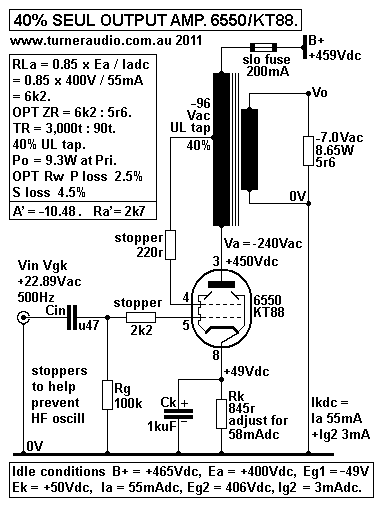
Fig 3 shows
a 40% SEUL output stage with the same Ea +400V and Ia 55mAdc,
and RLa = 6k2 The 40% UL taps to
better suit the majority of SE OPT sold with 40% UL taps.
UL gain = gm g1 x 1 / ( [ 1 / Ra bt ] + [ 1 / RLa ] + [ UL
fraction x gm g2 ] )
= 5.5 x 1 / ( 0.03125 + 0.1613 + [ 0.4 x 0.83 ] ) = 5.5 x 1 /
0.5246 = 10.48.
UL Ra = 1 / ( [ 1 / Ra ] + [ UL fraction x gm g2 ] = 1 / (
0.03125 + 0.332 ) = 2.75k
UL µ = gm g1 x UL Ra = 0.0055 x 2,750r = 15.125.
The Gain with pure beam tetrode = gm g1 x 6.2k x 32k / ( 6.2k +
32k ) = 5.5 x 5.19 = 25.56.
Screen gain = 4.31 from above Fig 4.THD reduction factor = 1 / (
1 + [ 4.31 x 0.4 ] ) = 0.367.
Fig 4.
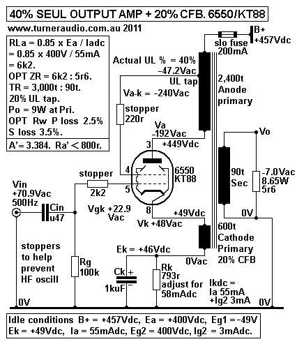
Fig 4 shows an SEUL output stage with 40% UL but also 20%
Cathode Feedback, CFB, from the OPT.
Its operation can be analyzed for those with above average
intelligence. If I spend another 4 hours writing
all the boring equations I may assume few would have any
interest.
But what we do have in Fig 6 is what I consider the King
Of SE output stage configuration because it
makes 6550 behave quite a lot better than triode mode and better
than a 300B, which is a real triode
capable of 9W, and I've never found this configuration to ever
sound bad.s
The OPT transforms the 5r6 sec load to become 6k2 load
which is between anode and cathode.
The primary has two windings with 80% of its turns between anode
and B+, and 20% of turns between
cathode and Rk+Ck biasing network. The two windings are well
interleaved with all others so that where
Va-k = -236Vac, there is -188.8V at anode and +47.2Vac at
cathode. A tap on anode primary is at 20%
of all turns away from B+ so that -47.2Vac is applied to screen
as 1/2 of the UL connection.
The other 1/2 UL connection is because the cathode has 20% of
all turns and the Vg2-k = -94.4Vac
which is 40% of the total Va-k of -236Vac. The UL gain = Va-k /
Vg-k = 236V / 22.51V = 10.48, which
is exactly the same as the normal 40% UL stage in Fig 5.
However, Vin is applied between grid g1 and 0V so that to
get Va-k 236Vac, Vin = 69.714Vac.
Therefore the CFB winding reduces UL gain from 10.48 to 3.84, a
reduction factor of 0.367, which is
about -11dB. This much local NFB has a profound effect on THD
and Rout. I calculated Rout = 683r
( effective Ra' ) which is about 1/4 the Rout for Fig 5 UL Ra of
2.75k. The calculated effective
µ = Vac / Vin without any load = 3.786.
Remarkably, to check if was correct, I calculated gm of
this set up = µ / Ra' effective = 3.786 / 0.683k
= 5.54mA/V, exactly what I expected it to be.
The THD reduction factor for the whole set up = 0.119, or
-18dB. Therefore, if there was 12% THD in
pure beam tetrode mode at 9W, THD with this set up should be
1.4%. Rout at secondary terminals including
7% winding resistance = 1r0.
Anyone building such an output stage will need to think
carefully about how to drive the 6550 grid with
69Vac and with similar low THD as the output stage. The
usual method I recommend is to use a an
EL84 in triode mode with Ia = 12mAdc, and Ea +300V and with 8k2
+ 40H choke to a +400Vdc supply.
This will give THD < 2% at 70Vac.
The THD of output stage will be mainly 2H. The EL84 triode
driver will also make mainly 2H, and this
will cancel the 2H of output stage to give truly remarkably low
THD, even before any GNFB is applied.
In some amps I have made using these principles, I have applied
about 10dB GNFB which reduces
Rout to less than 0.35r, and reduces noise and THD and IMD to
negligible levels. The SE32
is an example.
The use of UL taps with CFB can be applied to mainly class
A Push-Pull amps if there are suitable OPT
connections for both UL taps and a separate CFB winding. Most
existing OPTs in existing amps have only
UL taps if any, and OPTs with CFB windings giving between 12.5%
and 25% CFB must always be specially
wound, raising their price to at least 3 times the price of a
similar sized OPT from Hammond Manufacturing.
But in quite a number of amps I made, I have not
used UL taps with CFB windings and have only
used CFB. The most famous use of "local OPT CFB" in amplifiers
was done in Quad-II power amps during
1950s. Quad's invention was called the Acoustical Connection.
The CFB winding had 10% of the total turns
in the OPT primary and had the screens taken directly to a
filtered B+ supply rail.
The Quad-II design enabled a pair of KT66 to make 22W. The 10%
CFB reduced the high Ra of KT66
tetrodes to same as triodes so in effect the CFB did the same as
a 100% UL connection would achieve,
ie triode connection. But with 10% CFB, the KT66 gave twice the
Po as triode connection could give.
Use of any UL taps was seen as an unnecessary complication. So
with 10% CFB, THD was as low
as triode for low Po, and driving the KT66 grids was no more
difficult than driving KT66 strapped as triodes.
In Quad-II amps the B+ is at about +365V and Ek cathode
biasing = +28V, so Ea was about +337V.
The Eg2 was also about the same, and there was no advantage to
have Ea higher than Eg2.
The 2 x KT66 have Pda = 22W each so maximum class A is about 15W
at output, and only if twice
the load value is used as labelled. These old amps can have OPT
strapped to match 16r or 9r,
where anode RLa-a = 4k0 and Po in class A = 8W with up to 22W in
class AB. With RLa-a = 8k0, loads
must be 32r or 18r, and 18W is available in nearly pure class A.
Who has 32r or 18r speakers? - Nobody.
Unfortunately, Quad didn't provide a publicized 4r0 connection
at OPT which could be used with 8r0 to
give RLa-a = 8k0 where the performance then very good indeed.
OPT losses are high. and you have only 18W.
How does one take best advantage of the Acoustical?
In 1995 I built my first version of 8585 with 12.5% CFB
windings and 4 x GE6550A per channel.
It gave up to about 65W AB with 38W in pure class A with each
tube having Ea +400V and Ia at 60mAdc.
THD with some UL taps was less than 1% with no GNFB.
The later version of 8585
for 2006 measured similarly well but gave 100W class AB
with KT90EH.
The Ea = +470V, and Eg2 fixed Eg2 = +330V. I found I could idle
the KT90 at 33mAdc each for idle
Pda = 16W; the tubes have lasted remarkably well and sound is
utterly blameless.
The heat generated in the screen grid wires is much less
if Eg2 is kept low and the lower Eg2 means
that the Eg1 bias -Vdc may be a lot less than where Eg2 was up
with Ea. If the amp is a mainly class
A type with cathode biasing we don't need to have such a high Ek
which means less heat is wasted
in Rk, and the B+ may also be lower to accommodate the Ea + Ek
required.
Fig 5.
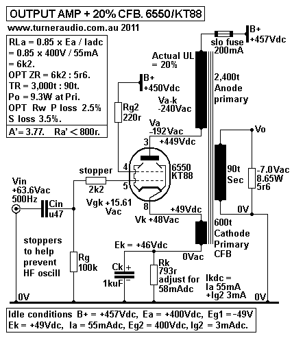
Fig 5 has no UL tap. There is +48Vac at cathode
and -192Vac at anode with Va-k = -240Vac.
With fixed Eg2, Vg2-k = -48Vac and the 6550 gain = 15.37, same
as for 20% UL. The 20%UL µ = 27.88,
and 20% UL Ra = 5,070r. The DF = 5,070r / 6,200r = 0.818, and
not as low as can be had with CFB or triode.
What is the Ra' with CFB?
20% CFB Ra = UL Ra / ( 1 + [ UL µ x ß ] ) = 5.070r / ( 1 + [
27.88 x 0.2 ] ) = 771r.
This is less than the 1.16k for triode. ( To get Ra' equal to
triode at 1k16, the CFB% would have to be about 15%.)
The price to pay for the CFB benefit is the increase of input
Vac to the output stage. However, this is very
easily done and the benefit of CFB outweigh the costs.
The 20%CFB DF for RL 6k2 = 6k2 / 770r = 8.05.
The open loop gain with RLa = 6k2 = 15.34. With 20% CFB, THD
reduction factor = 1 / ( 1 + [ 15.34 x 0.2 ] )
= 1 / 4.07 = 0.246, nearly -12dB so that if THD was 12% at 9W
without any NFB, then with CFB it should not
exceed 3%. Vin max with 20% CFB = 62.6Vac, and gain with CFB =
-236V / +62.6V = -3.76.
The CFB µ with no RL = -236Vac / +55.66V = -4.24. This means the
6550 with 20% CFB is behaving very
much like a 300B with similar µ and Ra. But the CFB will be much
more linear. The absolute max anode Po
max without OPT losses = 9.4W to 6k2, for Va = +/- 341Vpk, so Ea
at +400V is OK to allow Ea min = 59V.
If the load line for 6k2 is done using 6550 triode curves, and
to get same Po, Ea must be +510V, and with
Ia = 55mAdc, Pda = 28.0W, with anode efficiency = 33%, about the
maximum possible for a power triode.
The triode will need 54Vrms of drive to g1. The use of CFB gives
less THD than triode, higher damping factor
and idle Pda = 22W, with drive to g1 = 69V.
Overall result for 20%CFB of Fig 7 is very close to Fig 6
with an additional 20% UL tap. But the magic of
the screen tap reduces the odd number H in THD spectra, so
before the CFB gets to work, the 6550 is well
on the way to having triode THD spectra.
Using 20% CFB with screen g2 bypassed to cathode with
el-cap is also possible. g2 may be fed by a choke to B+.
Effective Ra' = Ra / ( 1 + [ µ x ß ] ), where Ra and µ
are for pure beam tetrode, ß is fraction of CFB.
This example, Ra' = 32,000 / ( 1 + [ 176 x 0.2 ] ) = 883r.
Open loop Gain, A = µ x RL / ( RL + Ra ). For RLa = 6k2,
A = 176 x 6.2 ( 32 + 6.2 ) = 28.56.
Closed loop gain A' = A / ( 1 + [ A x ß ] ), This
example, A' = 28.56 / ( 1 + [ 28.56 x 0.2 ] ) = 4.25.
Amount of applied CFB = 20 log ( A/A' ), this example =
16.5dB.
Open loop distortion of an SE class A beam tetrode 6550
at 9W may be 12%, with Ea and Ia conditions shown.
Expect THD = 3% with CFB. But although this seems good, the pure
beam tetrode has a large number of
even and odd H products, and these are merely reduced with the
CFB. If the screen is taken to a fixed Eg2,
the harmonic spectra change favourably because of the screen FB
action and my experience tells me to never
bother with bypassing screens to anode with CFB windings. I
believe the Acoustical or UL + CFB to be
superior to pure beam tetrode with CFB. in my SE35 with CFB from OPT
with EL34, I run Eg2 lower than Ea.
I found this made THD no worse, and allowed easier biasing and a
lower B+. In my PP 8585
I also have Eg2
lower than Ea and THD was less than use of a UL tap where Ea was
at +470V.
McIntosh should be mentioned because their amps have 50%
CFB which means anode and cathode windings
have equal number of turns. The total primary turns are
the same as for those used in a normal PP OPT with
no CFB. The screens of the 6550 in MC75 are taken to anode
connections of tubes on opposite sides of the
PP circuit thus allowing pure beam tetrode operation with CFB.
MC75 could be altered for lower max AB Po
= 50W, with Ea = +400V, and Ia = 55mA like my SE example here.
With screens taken to a fixed +400Vdc,
the 50% CFB gives 50% UL operation. The input to each output
grid will be about 145Vac, as in all MC amps.
McIntosh use a bootstrapped driver with 12BH7, and a lot
of GNFB to force everything to give outstanding
technical results which led to their use in countless recording
studios to drive cutting heads to make LPs.
I do not think there are sonic benefits from the McIntosh
connection with most listeners. EAR-509 was another
brave attempt at using a McIntosh type of output stage with 2 x
PL509 forced to make 100W. Unfortunately,
after rewiring a pair of these horrors, I found the sound from
an old fashioned UL amp with max Po 45W
was better, probably because the initial class A was about 15W,
but only 1W with the EAR-509.
Most people may assume 10%+ CFB windings with a fixed Eg2
will always be more effective than any
UL taps to reduce the effective Ra and reduce THD of beam
tetrodes or pentodes and while avoiding the
need to have grid drive exceeding 75Vrms.
The negative feedback in triodes or multigrid tubes due
to the electrostatic voltage effects is not a
perfectly linear application of NFB because the current/voltage
transfer function in vacuum tubes is not linear.
The anode current change for a grid voltage or anode voltage
change is proportional to the square root of a
number cubed. Professor Child described triode "self regulation"
better than I can in Terman's 1937 book,
Radio Engineering. The use of local NFB with external linear
elements such as resistors or transformer
windings delivers the effects of NFB more linearly than occurs
in the tube.
To Basic Tube 5
To Basic Tube 4
To Basic Tube 3
To Basic Tube 2
To Basic Tube 1
To index page