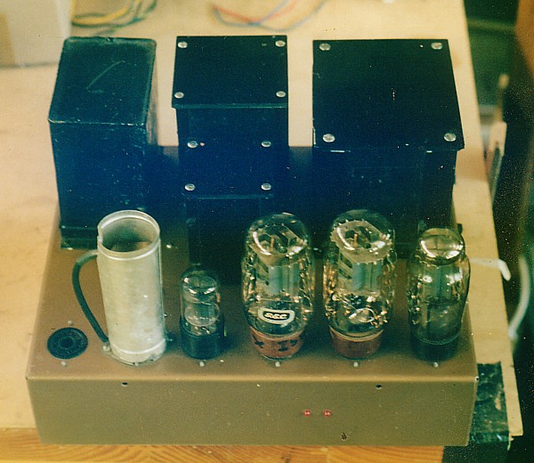
LEAK AMPLIFIER RE-ENGINEERING.

This page has the following content :-
General comment on Leak amps and 1955 design  considerations.
Fig 1. Leak TL12 on the work bench.
Fig 2. Leak TL12 upside down on the work bench.
Fig 3.
Schematic of the original Leak 1954 TL12 , carefully re-drawn for everyone who can't read the old copies.
Fig 4. Schematic of the Turner Audio Reformed leak TL12. 
Fig 5. Graph of the frequency response for the TL12 with the circuit mods, bith without global NFB and with global NFB.
Fig 6.  Graph of power output versus RL, Leak TL 12.
Comment on set up, class of operation, UL or triode ?, speaker matching, and the use of KT88, 6550, or KT90 preferably
in triode for the best performance. 
                                        ------------------------------------------------------------

Over the past 10 years I have had a few Leak amplifiers brought to me for repairs or for some slight re-engineering.
Like many amplifiers made in the 1950s the parts within such amps are now 50 years old and unless carefully serviced
each year over all that time then there definately will be faults with capacitors and resistors, and it is prudent to
completely rewire the amps at least if nothing has been done when you find an old one that has been parked
in an attic or basement for 40 years. However, like many amps 50 years old, the functions of the amp could easily
be improved to take advantage of the improvements in quality and reliability of modern metal film resistors,
capacitors, and many other parts.
Original Leak amp quality was subject to bean counter restraint and thus sustained serious design compromizes.
Its easy to look back at what could have been made, but in 1955, Harold Leak must have been worried
about what Quad or Radford might be trying to produce to dominate the market, and accountants in all
companies had a favourite word to design engineers....."NO!".....

Modern expectations of tube amps include that they be reliable, need little service, and that they produce
accurate dynamic hi-fi second to none and with all warmth in the recording carefully preserved.
Many tube and solid state amps don't quite meet all those expectations.
Many old amps such as those from Leak, Quad, Radford, Dynaco, Luxman, etc, were simply never originally
engineered to the high standards possible in 1955. For example, little regard was given to the recommendations
within the Radiotron Designer's Handbook, 4th Ed, 1955, about output transformers.
Just about all the major maufacturers skimped on output transformer quality.
In the early 1950s, Mr D.T.N.Williamson spoke a lot about what was required in a good output transformer and made public
his landmark design for a push-pull output transformer which had really high bandwidth, low phase shift,
freedom from saturation, and low winding losses.  The exact details of his OPT design is within the RDH4.
Nearly all the mass makers ignored Mr Williamson.
Anyone who didn't ignore him and persisted with with trying to sell 16 watt amps using KT66 in triode all went broke,
because the post WW2 marketeering insisted people buy high power, which they mostly didn't use
because the speakers of the era were typically 95dB/W/M.

One may wonder why bother re-engineering such ancient old junk but in fact it is worth it, and the lack of output transformer quality does not prevent good music being heard from these old amps.
To buy a pair of new tube amps now may be quite expensive, and sometimes the new quality is no better internally
than what was used in a 50 year old Leak, despite the printed circuit boards and fancy appearance.
Good listening is the product of the well done circuitry, and isn't improved by good looking  cosmetics.

Leaks can be rewired to include a few appropriate techniques to address the original shortcomings in the original
amps and if used sensibly can provide sound quality second to none for most listeners wanting a few watts at home.

In 2005 I re-engineered a Leak amp for a customer and I will relate what changes I made and why.

Fig 1, Leak TL12 , a classic mono bloc amplifier, 2005
Leak amp on the work bench, 2005.

Here we have a famous Leak amp  from around 1955 sitting on my work bench and as you can see it has
two leds located in the side of the chassis below the two KT66 power tubes.
All major parts on top of the chassis have been retained to keep the retro look.
The empty tube socket to the left side is where the preamp plugs in for its power
and the feed signal for the power amp.

Fig 2. Leak mono bloc turned upside down on my bench, 2005.
leak mono amp underchassis wiring, 2005. 

The image shows all the replaced R&C components. The white active protection board is at the rear of the picture,
and I have included a schematic at the bottom of this page. There is an additional 7VA auxilliary power transformer to the rear left, and additional filter caps on the rear right.


Fig 3. The 1954 original schematic of Leak TL12 mono bloc amp, which I re-drew in feb 2006.1954 Schematic tl12 re-drawn 2006.

All the digital file copies I had of the original schematic from the Net were unreadable on the screen and useless if printed.
My own original 1954 paper copy became un-readable if anyone tried to copy it, mainly  because Leak refrained from using  large clear lettering on their  information sheets. I can only suppose that Britain was still rather short of ink after WW2,
or that british bean counters restricted the size of their lettering since small letters are cheaper to have printed than large ones.
So I red-drafted the original schematic as exactly as I could so you can read it and it may print out OK.  This was during
the learning process with MS Paint, which is what I now use to prepare schematics.
The original schematic was a little too simple for my liking, since this amp was not unconditionally stable. Modern people now expect all amplifiers to never oscillate or behave badly.

Here is the Reformed leak TL12 schematic......
Fig 4.
Modified Leak TL12 schematic, 2005.

The above schematic has all the listed mods noted on the schematic.
The numbers I have used for components are not the same as in the 1954 original schematic.
The improvements made this Leak amp unconditionally stable and completely unlikely to oscillate at any frequency under
any load condition, or when turned on without any load connected.
The amp can have the KT66 either Ultralinear or Triode connected without changing the NFB arrangements.
Fig 5.
Graph for Leak TL12 response.
The above graph shows the effect of applied NFB on the amp. The HF response is shown with various capacitance
values used for a load along with the equivalent load which mimics Quad's ESL57.
Notice the peaking in the sine wave response above 20kHz with capacitance loadings.
This shows that the amp is barely able to remain stable. Any square wave will also have considerable over shoot and ringing cycles before settling with capacitor loads. But with all the new networks used in new schematic I managed to make the the margin of stability sufficient and the amp will NOT oscillate at HF like it surely does with the original 1954 schematic.
The 1954 amp also oscillated at LF without a load but the re-arrangment of the RC values between v1, and V2&V3
in my 2005 schematic stopped that problem.
Fig 6.
Graph for Leak TL12 po vs RL.

KT66 cathode resistances were increased from the 1954 original 600 ohms to 750 ohms to reduce the idle Ia
to about 48mA because I found that I had a higher B+ than in the original amp. The dissipated power in each KT66
is still only 21 watts approximately, for 42 watts total and the class A maximum power is thus
about 17 watts in UL into 20 ohm load and for triode the pure class A maximum is about 12 watts.
For UL, at 8 ohms only 7 watts of class A is available with the remaining 20 watts in class AB
There is also only 7watts of class A into 8 ohms , and with the remaining 7 watts in class AB.

The amp as set up with secondaries wired as shown was meant for a customer who said he had a 16 ohm speaker.
For 16 ohms there is 11 watts of pure class A in triode or 22 watts AB with including 14 watts of class A.

The triode instaneous AB1 maximum is 15 watts into 5 ohms but with continuous sine wave it is 13 watts.
The use of loads less than 8 ohms isn't recommended.
These figures should not mean much unless you have speakers rated for only 85dB/W/M and you like huge levels.
Most ppl would find these amps to sound very well with moderate levels and speakers above 90dB/W/M sensitivity
and above 8 ohms.
About 7 years ago I did a similar modification to a pair of TL12 and my client and I tried one amp in triode,
and one in ultralinear using a good souce and fairly sensitive 15" dual concentric 1969 Tannoy speakers.
Not the slightest change in sound could be detected between triode or ultralinear, and more tests
since confirmed that I can safely conclude that either modes of output tube operation makes not the slightest difference in sound quality; either way its excellent, well detailed, smooth, dynamic, creamy, warm and never dull, frumpish, or euphonic.
The pair of leaks I altered 7 years ago eventually wore out their motley collection of 40 year old aged KT66
and the owner had me change the KT66 for Sovtek 6550 which I wired in triode. The triode connection of either
6550, KT88, or KT90 gives about the same class AB output power as the KT66 in UL, and may be plugged into
the KT66 sockets without any circuit alterations.

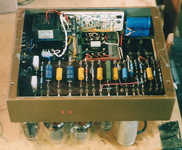
The leak TL12 OPTs are very fragile, with very thin wire in the 4,000 primary turns and hence my use of an active protection circuit board to warn an owner of bias balance problems.

Fig 7.
PP amp protection circuit.
 

Back to Index Page