LOUDSPEAKERS 2, DIY.
Content :-
Design details, Sublime speakers shown at Loudspeakers 1, premium
quality.
Design details, Single box full range floor stander speaker with
full explanations
with reasons for using this design.
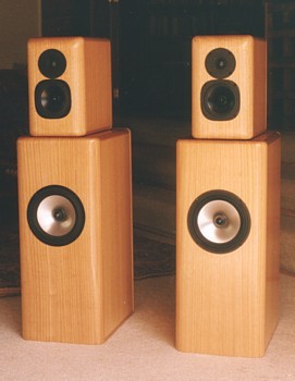
Image 1, SUBLIME from 2000.
Drawing 1. Sublime Bass speaker box. 
Drawing 1 shows all construction details for the bass box using
40mm thick plywood or multiple layers of ply
such as 2 x 17mm plus 4.5mm finishing ply, or from 40mm joined
hardwood planks which have been kiln
dried to prevent severe expansion and contraction.
In my original Sublime from 2000, I used 2 layers of 17mm pine
marine grade plywood for top, bottom and two sides,
with a final 4.5mm thick veneered finishing plywood. To hide end
grain of plywood at rounded corners I used solid timber
quadrants well fitted and glued. For all veneers and solid timber
I used Victorian Mountain Ash which I found easily
available locally.
It is possible to use veneer finished particle board and MDF but
these products are very inferior products to real plywood.
I have been told that bamboo plywood has become very preferable
but I have yet to see a sample in my hand or try to
work with it and until I am proven wrong, bamboo ply is a cheap
low quality product which may provide some cheap
solution to the huge future increase in demand for some sort of
timber finish that is affordable by teeming billions
becoming more able to purchase the pretentious western way of
life.
DIYers may not be so good with woodwork, and since having a nice
finish that feels like touching a Norwegian Goddess
does not make the sound any better, I could suggest all panels can
be made using a single layer of suitable plywood
40mm thick, planed, filled, and sanded smooth to give the shapes
shown, and then given several coats of acrylic water
based semi gloss house paint with color chosen by the missus. Such
paint is best applied using a small 100mm long
fine hair roller which will leave no roller or brush marks, and
leave a slightly orange peel texture to the paint surface.
Try it, you will like it, and save yourself a pile of time and
unnecessary expense of trying to be pretentious.
My bass box uses one 210mm SEAS driver unit with Vb = 50L to get
maximum LF extension. Some 200mm bass
drivers work OK to make low bass in only 40L, so for two drivers,
80L would be OK. The bass box Vb is easily
changed during the design stage, and for 80L instead of 50L, with
two bass drivers in the front panel, the internal
front to rear box dimension is simply increased from 400mm to
640mm. And BTW, the bass box recipe as I have
it could be used to make a good sub-woofer.
Drawing 2. Sublime Midrange and Tweeter box.
The Supreme two box recipe using rectangular shapes will give
excellent sound. One older customer of mine
built a very good pair of enclosures using 35mm thick Australian
blue gum planks normally used for roof trusses.
This material has a density close to 1 gram/cc, much more than
pine plywood at about 0.55 gram/cc. If real timber
is used it must be kiln dried, not just air dried lest it shrink
unevenly too much after the speaker is built.
My Supreme and Sublime have laminated ply sides, top and bottom,
with real hardwood timber planks for
front and rear panels. Fronts are held to sides with internal
aluminium angles with slotted holes and many wood
screws with a foam gasket, thus allowing real timber to expand and
contract across more rigid sides+top+bottom
which does not expand/contract because it is plywood. Rear panels
are also hardwood real timber, 32mm thick,
with 75mm long screws from the outside and a foam gasket used
between the join which squeezes up to less
than 1mm thick.
The foam join also absorbs vibration "around the corners".
The most important property for speaker boxes is to make them
acoustically dead so panel vibration, internal
standing waves, and coloration of the music is minimized. The
technique is the opposite of building a cello.
The dome tweeter in a 20L box. When using more MF drivers, the Vb
needs to be increased proportionately.
If say 4 x 5" Peerless MF units, type P850489 are used with two
Peerless HF 810921, then box Vb = 36L,
so oa sizes become 720mm x 238mm x 380mm. The D'Apolito
arrangement with Mf-MF-HF-HF-MF-MF
would be OK, and best with small dia HF now available, so that box
height could be kept under 720mm, and
box Vb maintained by increasing the front to rear dimension. The
Peerless MF 4" 830881 plus HF 1" 810921
could also be used to keep box size smaller yet still give the
wanted 200Hz to 20kHz F range.
----------------------------------------------------------------------------------------------------------
For those without much skill or money, they might allow themselves
to make a full range floor stander
with a 3-way set of drivers. A couple of DIYers have done just
this and gained excellent results.
One fellow made his boxes as detailed below, then sent them to me
to have drivers installed and have
crossovers designed, built, and all fully tested. So I know this
idea works well.
Drawing 3.
The above speaker design features the following :-
1, Sloping sides to make the speaker tall enough for good treble
and mid-range height so that speaker
stands are not necessary.
2, Has enough total volume to form the TWO separate bass and
mid-range rear chambers to suit most
brands of available drivers, not just Peerless.
3, Sloping sides minimizes standing waves between sides inside the
enclosure.
4, The speaker shape is much less likely to fall over than a tall
narrow rectangle shape, and the speaker
weight with large base dimensions gives good stability without
needing floor spikes.
5, The project does require a diyer to be capable of working with
angles other than 90 degrees.
Although this is challenging, and more difficult than making just
one tall rectangular box, the acoustic
properties with sloped sides as shown will be superior.
6, The appearance is more interesting, and more functional because
the "pointy top" and well rounded
small width amount of front panel around the tweeter will minimize
diffraction and give a flatter frequency
response, better imaging, and and less "beaming".
7, The slope of the front baffle panel gives some vertical
alignment of voice coils.
8, The design is suitable for those extremely well skilled with
timber finishes or for those who may wish to
just apply paint.
9, The angle chosen for the "lean" of every side off the vertical
is the same so setting out the cutting of the
sheet of plywood, MDF or other material is fairly waste free. The
8 vertical panels shown should be able
to be cut from a single 1,200mm x 2,400mm standard sized sheet of
material. The cut out pattern is on the
above Drawing 3. As long as anyone adheres to the INSIDE
dimensions of the box, then the panel material
can be any timber type above at least 33mm. I personally do not
like 33mm MDF or pine particle board.
What I DO LIKE is marine grade pine plywood. It is not always easy
to buy from a builder's supplier, so
you may have to search around for it, and it costs more than MDF,
but the expense on good plywood is
minimal compared to all the other things you will have to purchase
plus the value of YOUR TIME.
OPTIONS.
Let us suppose you wanted to have say 150mm midrange and 250mm
bass. The box can have the same angles
of slope, and same overall height, but may be 30mm wider. The two
Vb would probably need to be increased
to say 25L and 65L. The front to back overall size would need to
be increased perhaps to 650mm, but you
would have to work that out yourself. The amount of plywood needed
will increase, and the number of braces
should also increase.
SPECIAL CHALLENGES.
Because the vertical panels all slope towards each then at the
vertical corners any two meeting panel joins
will not meet perfectly if the all edges are cut with "square
edges". The panel which butts to the surface of
another at a corner will need to be planed with a slight angle of
a few degrees, or slightly "beveled" to get
good meeting surfaces.
Even though the drawing looks quite simple, the woodwork is quite
tricky because of the angles of cut and
bevels involved. Some DIY carpenters will probably curse and swear
when they must return to the timber
store to buy ply more after cutting something wrong.
But a DIY person could indeed get all panels cut with square edges
but say +2mm larger in size all around,
so that the required edge beveling may be done using a hand plane
carefully to establish the required angles,
and so gradually get all 4 vertical panels to have straight
corners, and with gap free meeting surfaces that
will hold glue when applied.
The design aim is to create something above the ordinary.
While I am alive, I shall not imitate or promote mediocre speaker
designs and nor will I promote your
tendency to be lazy.
Remember the golden rule, check measurements 3 times, cut once for
plywood.
( If you measure just once, then cut once for FIREWOOD ! )
DIFFICULT GEOMETRY!
I can say that many will struggle to handle the geometry of these
boxes where there are almost no 90
degree angles. If have very poor woodwork skills, and you don't
have a good set of tools and a workshop,
then DON'T build these speakers.
Suppose you use two sheets of marine ply, each 1.2M x 2.4M and one
is 16mm thick and the other is
25mm thick, and you glue the two sheets together while laid out on
a dead flat surface, then you would
get a panel 41mm thick. You should be able to cut the 4 fronts,
backs, sides, tops and bottoms for BOTH
boxes from the 1.2M x 2.4 standard ply sheet size with little
waste. You may find you need some extra ply
for the dividing bulkhead and the braces, but this material can be
ordinary low grade ply of at least 17mm thick.
The weight of the two boxes will be about the weight of the 41mm
thick sheet = 1.2M x 2.4M x 41mm x
0.55gms/cc = 65Kgs. So each speaker with drivers will weigh about
39Kg.
1. TEMPLATE.
Before anything is sawn or glued, a full size drawing of the box
is produced on a spare clean blank sheet of
thin MDF material which becomes the TEMPLATE for the work. When
panels are cut to size and edges
planed to fit and they may be laid on the template to check sizes
and angles. Working with a template avoids
mistakes, and the first time anyone uses a template they will
appreciate it fully, and wonder why they didn't
use one before.
2. SMART ARSES might just employ a plan printer to enlarge my
drawing until it comes up to the actual
sizes, and they would then glue the full size drawing to a thin
sheet of MDF, or thin plywood to make the
template.
3. MY DRAWING was prepared in MS Paint with box dimensions TO 1:5
SCALE, using a scale ruler
laid over the PC monitor to adjust the line positions to the
nearest pixel. How it looks on your PC is anyone's
guess, but the .gif drawing shown be able to be reproduced in the
printer's image program and enlarged,
keeping the aspect ratio constant, and sizes correct.
4. CROSSOVER FILTER BOARD is not shown on the Drawing 3. The
filter board can be made using
12mm plywood about 180mm x 250mm and with all L and C and R parts
glued to the board with Selleys
401 silicone. Circuit tracks should be 1.2mm solid copper wire
soldered around 16mm long x 4guage
brass wood screws in 12mm ply.
Crossovers filters are fitted after box is finished and testing of
response is completed. These boards should
be screwed to the bottom panel on a layer of 6mm foam. The boards
and all their parts should be entirely
well painted with polyurethane varnish to all surfaces before
final installation.
5. SPEAKER TERMINALS should be for recessed 4mm banana plugs only,
because I don't like any other
type.
However, if you manage to break a 4mm banana plug off the end of a
cable it may be very difficult
to remove the end of the plug from the recessed 4mm socket unless
the rear panel is removed, and 1mm
hole drilled through socket to allow a peice of wire to be used to
pus the plug end out.
I like to have 4 terminals for using bi-wiring or bi-amping. These
should be set at least 40mm apart to
avoid letting strands of cables causing all to easy short
circuits. The detail may as I show in Drawings 1 and 2
above for my Sublime speakers. If binding post action is wanted,
use Drawing 1 detail where the posts fit into
a removable ply panel, and such binding posts are unlikely to all
too easily be snapped off when speakers
are moved around.
6. SETTING OUT shapes of vertical sides on the 1.2M x 2.4M bulk
sheet of ply should be done with care
and to allow for saw blade thickness, so allow 3mm between lines
if the saw is a 170mm circular type with
2mm blade cut. Don't try to cut beveled edges to panels, its far
to confusing, just cut all panels with a square
saw cut, and then apply beveling to meeting surfaces as try to
assemble panels. The assembly of ALL panels,
bulkhead and braces should be achieved BEFORE any glue is applied.
Rounding off external corners is
done after gluing and dowel fixing is complete.
7. FOUR VERTICAL PANELS should be joined at each corner after
careful adjustment of edges with a plane.
60mm long wood screws may be used to hold panels together
temporarily as you proceed. You will find
external surfaces at corners will need to be planed flush, but
leave that until all glued including dowels.
After the 2 sides, front and back are together, the back may be
removed, and bulkhead and braces fitted
and held by screws. The back is then re-fitted to ensure the
bulkhead and braces all fit with nothing binding
or causing bulges.
8. THE BULKHEAD should ensure the 4 vertical panels are at
90degrees to each other in the vertical plane.
9. TOPS AND BOTTOMS are shown fitting BETWEEN the vertical panels
so that the joins tend to be
hidden. The positions of where the tops and bottoms butt into the
front, sides and back must be well drawn
while setting out so that after planing tops and bottom edges of
verticals to make over all surfaces, your box
will stand straight, without any "wonky lean", or un-level top
surface.
10. My Drawing 3 shows the top and bottom panels fitting between
the vertical sides. But if anyone wanted
to fit tops and bottoms extending over the vertical panels, it
won't make much difference to the box volumes
of frequency behavior, and many DIYers would find the construction
easier. The height of vertical panels may
be kept at 1,000 mm, and with tops and bottoms fixed over this
height, the overall height 1,066mm, quite
acceptable. Dowels are later fitted vertically.
11. SPEAKER DRIVER HOLES in the front panel may be set out and cut
with a jigsaw before fitting
anything together.
12. BASS PORT HOLE in the rear panel may be set out and cut with
jigsaw before fitting anything together.
For this, you will need a 300mm long piece of PVC sewer drain
pipe, and the hole is cut and trimmed to
allow a horizontal pipe position, and a sliding fit, to that later
the port can be glued with top quality silicone
such as Selleys 401. The internal retaining block at the internal
port end can be fabricated later after
assembly and glued in then entries rounded up to prevent port wind
noise. The port length cannot be
determined until the bass driver is tested in the box. The port
and support block are fixed after driver tests
are complete, and access to internal block positioning is through
the front bass driver hole.
13. BRACES AND THE INTERNAL BULKHEAD between mid-range and bass
should all be fitted
and temporarily screwed in place when 3 sides are together, so you
can see what you are doing, before
the 4th panel is fitted. 75mm long phillips head screws about 10
gauge meant for particle board fixing
are ideal, and should be placed where a dowel is to be placed
later. I use lots of masking tape to hold
panels before drilling a 4mm hole for screws. I only have 2 hands,
and I wouldn't mind 3 more pairs.
14. WHEN EVERYTHING FITS WELL, mark meeting panels and items with
A & A, B & B so that
when temporary screws are removed, you will know what has to fit
together during the gluing procedure.
13. MARK OUT DOWELS. All positions for 8mm dia dowels need to be
marked out neatly in pencil.
14. GLUING UP EVERYTHING. Gluing may commence with one side panel
laid flat on the bench.
Use generous beads of PVA glue from a 1Litre glue bottle. Bring
say a front panel to lay against the side
and insert screws and tighten. Excess glue will overflow from
joints, which means you have plenty of
glue where its needed. Proceed to glue and screw another side,
then braces and bulkhead. glue the
back on, then top and bottom, and don't forget to leave anything
out!
Have a bucket of water and piece of towel cloth sitting ready to
wipe away excess glue on the outside
of the box. Leave it standing upright for a day so glue cures.
15. Fixing Dowels. Use only 8mm hardwood dowels. Cut enough 80mm
long x 8mm dia dowels for the
number required. Usually 8mm dia dowels are available at good
builder's hardware stores. Drill ONE
dowel hole 75mm deep using an 8mm drill, and try the dowel fit to
make sure the dowel is an easy sliding
fit, and does not need to be hammered into the hole and is not a a
sloppy and loose fit.
A day after everything is glued, the screws may all be removed.
The box will be fairly strong.
To ensure a 500 year life, 8mm holes are drilled 75mm deep where
the dowel positions are marked,
which should include where temporary screws had been used. Squirt
some glue down each dowel hole.
Get a 6mm dowel or "stick" and stir the glue around in the hole to
ensure all surfaces are wetted.
Twirl one end of each dowel in a pot of glue to wet the dowel well
before insertion. Slide dowels in
gently, and allow time for excess glue to rise around the sinking
dowel. Doweling done properly like this
are Fabulously Strong.
Wipe away excess glue, then leave all alone for a few says for all
to cure and DRY.
16. PLANING AND SANDING. The box will look messy, with plywood
edges and corners untidy,
and dowels partially extending outwards. Use a panel saw to cut
all dowel ends flush with panels.
Rounding all corners may be done initially with a hand held
electric planer. You should have enough
experience to plane off corners with course facets around a curve.
The facets may then be planed
further with a non-electric hand plane to make facets much finer,
and to make sure butt joints are nicely
flushed.
18mm to 12mm radius rounding to all corners is enough except for
the top part of the front panel where
the midrange and tweeter is located. So one can increase rounding
radius of 8mm at the bottom of front
panel to become up to 33mm radius at the top of the front panel
all around the tweeter.
Once you have planed it all, then comes the sanding. Hand sanding
is the best, and I suggest you have
a wall plasterer's hand grip sanding tool to which one can clamp
fine sanding paper. The trick here is to
use some 3mm foam sheet between the sandpaper and the tool plate,
and when sanding curved corners
the sandpaper will wrap around the curve and remove all facets
left by planing. With care, and the use
of increasingly fine sand paper up to 800 grit size, you should
get the most beautifully smooth and
flawless finish, like the shoulder of the Danish Goddess.
17. SPEAKER HOLE REBATES. Most hi-end speakers have the speaker
drivers neatly fitting into
a shallow recess around the driver holes, called a rebate. It
looks pretty, but does nothing to improve
the sound, and where I have used SEAS drivers I have not bothered
to rebate driver holes and thus
fit drivers so their outermost metal flange is flush with timber.
SEAS flanges are fairly thin, and look
tidy, so thus rebates are not necessary. If you are going to
rebate for the drivers, now is the time, and
you will need a very steady hand with a router, or perhaps a
curved chisel, and a very careful use of
sand paper to ensure all looks perfect after finishes are applied.
The drivers will need to be tried in you
cut outs to ensure they will fit OK allowing for compressible 3mm
plastic foam. Using routers or tools
over sanded surfaces requires you cover around the holes with
masking tape to prevent stray damage.
The better you want the finish, the more you need to think ahead
and the harder you have to work
and more time you take.
17. FINISHING OFF. If you have done an exceptionally fine amount
of work with plywood, then
you probably will have open timber grain and stray gaps and holes.
I suggest some turps based grain
filler to be rubbed in with a fine cloth, and the filler color
should match your timber color. Excessive
smearing of filler must be avoided, and surfaces rubbed clean as
filling proceeds, so that only open
grain and gaps are filled. Boxes should be left alone for a couple
of days for filler to cure.
Boxes can then be dry sanded with 800 grit to remove any
upstanding wood or fibres. If all looks well,
and no more filling or sanding is needed, then semi-gloss
polyurethane varnish may be applied with a
fine new clean brush. Make sure polyurethane is thinned with 20%
white spirits. 5 coats are
recommended, with 3 days between coats and fine sanding with 1,200
paper lightly to remove surface
fur between coats. A dust free environment is essential, so apply
varnish late at night in the workshop.
The final surface is allowed to harden for a few days. The surface
may be further rubbed up with the
finest steel wool you can find plus some danish furniture oil
which should not dissolve the applied
varnish. Use fine clean cloth to rub off excess oil and you should
have a very good surface.
Use the WinISD to confirm drivers chosen will work OK in box
volumes. When using say Peerless
5" 831882 as a midrange for F above 150Hz, there is no need for a
large critical Vb for best ported
bass performance and closed box design is OK. As the closed box
size is reduced, the resonant Fo of
driver in the box rises and could be 90Hz. The top chamber Vb of
about 7 litres should work OK and
should be filled with high density polyester wool which is
normally used for acoustic damping in timber
frame walls. Lower density insulation may be used but packed tight
enough halve the loose volume.
The bottom chamber is about 47 Litres allowing for ports and
braces etc, and about right to get a
good bass response from many modern 8" dia speakers such as the
Peerless 831868 or 830869.
The wool filling should be light density and fill should not be
crammed in but about 1/2 fill the ported
chamber without obstructing the port opening. It should be secured
with a few staples and threaded
up around the braces of the enclosure.
Crossover filter design is at
Loudspeakers 3,
Crossovers
To
Loudspeakers
4, measuring response & impedance
Loudspeakers 1,
New
Loudspeakers
directory
Back to Index Page