SE32W
with 13E1, July 2008.
For those not wanting to read about ancient history dating back to
2008, they may go to the
2012 version
of SE32 amps.
The following history last edited 2017 has valuable info including
Fig 2 which has all details
for a very good SE OPT to suit 1 x 13E1, or 3 x KT88 / 6550.
In 1997, I built the 22W SEUL amps using a single 13E1 in single
ended ultralinear mode.
The details are well covered in my web page on the SEUL 25W. The SEUL amps
pleased anyone
lucky enough to hear music piped through them.
In 2000, I demonstrated the SEUL amp to the Audiophile Society of
NSW at a Sydney venue.
The 30 people present very much enjoyed the experience.
Since 1997, I have increased my experience of using local negative
feedback in amplifier output
stages, with less reliance on global NFB applied from an OPT
secondary to an input tube cathode
in the traditional manner.
I first applied the idea of local CFB in SE output stages way back
in 1994 when upgrading 5W
amps in an old stereo AM radio which had EL84 output tubes. I
applied the idea for a much more
powerful SE amp with 4 x EL34 in my
SE35W monoblocs.
A customer of mine who had bought a pair of SEUL 22W amps had
borrowed another customer's
SE35 amps and he thought the SE35 to be slightly more accurate and
detailed. It is not uncommon
for audiophiles to lend their amps to each other for comparisons
occasionally.
I wondered if any better sonic and technical performance could be
had from the 13E1, and I had
suspected it to be possible ever since 1997 but had not fully
explored the possibilities and
practicalities. My customer with SEUL 22 has always found that
other projects I have built for him
resulted in a worthwhile and pleasing outcome so he went ahead
with the change from the ultralinear
operation with screen feedback from tap on the OPT anode
primary winding to having the primary
divided into two windings with 66% of turns for the anode and 33%
of turns for the cathode for
applied cathode feedback.
He had also purchased a pair of my Sublime speakers, also
described in my website page on
loudspeakers-new.
The original SEUL amp was in fact capable of about 22W into 8 ohms
and about 25W into 4r0.
But with 4r0 there was more than twice the THD than with 8r0 and
because the Sublimes had an
impedance of about 5r0 average, I thought a change to the output
transformer ratio would give a
much better load match to the 13E1 and thus reduce the distortion
and give a higher maximum
output power of 32W because of increased anode efficiency with a
much lower screen dissipation.
The sound of the new amp circuit is very clear and natural, but
never clinical or blandly cold,
and conveys the recorded warmth of a real live performance to give
high emotional engagement
with music that is the hallmark of a good tubed system. Bass is
tight and gives the music its
foundation, treble is sweet, with midrange that is glorious
without being "euphonic" - ( a commonly
used and vague word used by audiophiles to often describe SE
Triode amps with little bass, rolled
off treble, and no loop FB and some ring tones from vibrating
microphonic grids/cathodes in directly
heated triodes ).
Rather than wade through the changes to the SEUL22W schematic in a
laborious discussion,
I will simply provide the SE32 schematic I used and explain how it
works, with some provisos
and notes about limitations etc. People are then free to compare
the SEUL22W to the SE32
schematic, and are free to adopt the principles of the operation.
Tube amp design is somewhat flexible.
Fig1, for 2008 amp.
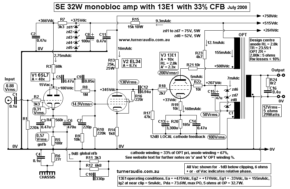
Fig1 shows the audio circuit with input V1 6SL7, driver V2 EL34 in
triode, and output V3 13EI.
V1 input stage, 6SL7.
C1+R1 form a high pass filter with pole at 7.2Hz to keep out dc or
very low F signals.
V1 Input stage signal is applied to the 6SL7 grids.
There is a very mild amount of 9dB of global negative feedback
from OPT secondary applied to the
cathode via FB resistance divider, R5 and R11,R12.
The voltage difference between the grid input signal and cathode
feedback signal is amplified 47 times
by the 6SL7 and applied to the network beginning with C5.
The network after C5 has a shelved response at LF and HF to reduce
the 6SL7 gain and phase shift
at frequencies where otherwise oscillations might occur below 10Hz
or above 60kHz because of the
use of the global NFB.
The 6SL7 is among the world's most linear triodes and easily
produces the 15Vrms at very low THD
required by the next EL34 driver stage. V2 Driver stage, EL34.
The EL34 is triode connected and has a gain of about 8.7, close to
the µ of EL34. I had hoped to use
a choke plus resistance to feed the EL34 with anode dc so that
this gave a high impedance dc feed to
the tube but there was no room to put any filter chokes, and very
little time to do it. In 2008 I created
a +750V supply rail for the EL34, and used a simple 25k resistance
R13 to convey Idc to the anode
via R13.
The following grid bias R17, 47k, is bootstrapped to the cathode
FB winding at near 0V potential.
This causes the its loading value on EL34 anode to effectively
appear as approximately 203, and the
total anode load for EL34 becomes 25k in parallel with 200k in
parallel giving total of 22k.
The EL34 has Ia = 16mA, and Ea = 320V approx, and maximum anode
signal = 180Vrms at
about 2.5% of mainly 2H. 130Vrms is needed to drive the 13E1 grid
to clipping level and at this
level the EL34 produces only about 1.8% 2H distortion and it could
not be made more linear easily.
This 2H has a phase relationship with fundamental frequency such
that there is substantial cancellation
of the 2H produced in the output stage, and most most effectively
where loads are less than rated
nominal, when output stage distortion becomes highest. All SE amps
where you have a single ended
triode driving a single ended output tube do have some distortion
cancellation naturally occurring
between the two stages. Usually the 2H cancellation does not
result in a useful amount of 2H reduction
because output tube THD is typically 4 times that of the driver
tube at all levels up to clipping.
In this amp and the SE35, the use of local CFB windings on the OPT
in the output stage reduces the
output stage distortion to similar percentages to that of the
driver stage and at all levels so the
cancellation then becomes a very effective way of reducing
distortion without having to use global NFB
to reduce the distortion. The benefits of the CFB are similar to
the benefits of 2H current cancellation
in PP balanced amps, but in this SE case there is voltage
cancellation instead of current cancellation.
In the SEUL, global NFB is about 16dB, so all distortions get
reduced by a factor of about 1/6.
So where there is no global NFB, there may be 6% THD, including
slight 2H cancelling between
driver and output stage.
When GNFB is added, THD is then reduced to just under 1%. In the
case of amps with substantial
amounts of CFB such as the SE32 here (and SE35), the THD without
GNFB varies with load value
but is kept under 1.5% for a range of useful loads because the THD
of the driver tube cancels the low
THD of the output stage for low loads where most THD occurs. Such
2H cancellation is impossible
with a pure beam tetrode, pentode, triode or UL stage without
local CFB because all such output
stages have over 5% THD without CFB, and the driver triode does
not make enough THD for any
significant cancellations, and in fact the IMD produced in the two
stages without any NFB at all
probably sounds worse than where THD reduction in the OP stage is
achieved within the OP stage.
Trouble understanding that? Let us assume we have just two
hypothetical amp stages in cascade,
driver and output stages, where OP tube gain = 2.3 times which is
the low gain of an OP tube
with a lot of CFB present. Gain with CFB = Va-k / Vg-0V.
Consider the operation at medium power levels well under clipping.
Consider Va-k = 230Vrms
anode to cathode signal applied to an OPT and there is 1.0% of 2H
present. The 2H signal =
2.3Vrms. Suppose the driver stage also produces 1.0% 2H, where its
anode voltage is say 100Vrms
which is applied to the OP tube grid. The 1.0% 2H = 1.0Vrms. The
output stage amplifies the
100Vrms of grid signal to produce Va-k = 230Vrms, and also
amplifies the driver tube 2H of
1.0Vrms to produce 2.3Vrms of 2H. In such a hypothetical
situation, if the amplified 2H from a
driver tube equals the 2H produced by an OP tube are equal, then
complete cancellation of 2H
occurs and no 2H is to be measured. Magic seems to have occurred.
In practice, if you have TWO lots of 2H signals present, and if
the RELATIVE PHASE of 2H to
fundamental frequency produced in driver is the same as that
produced in the OP tube then the
phase inversion that occurs in the OP tube will cause the two lots
of 2H signals to have opposite
phase, so there will theoretically be the difference between the
two lots of 2H at the output of the
output stage.
The actual difference is slightly affected by phase shifts caused
by C and L effects in couplings and
OPT, but the reduction in 2H may be very substantial. However, 2H
cancelling with tetrode or
pentode OP stages using NFB has limitations because the 2H
relative phase in such tubes is same
as a driver triode where OP anode loads are low, and then become
opposite at high OP anode loads.
The 2H of tetrode/pentode tubes is high at low RLa loads, then
reduces to zero at some middle
RLa, then increases as RLa goes higher, and with relative phase
that is opposite to use of low loads.
( The tetrode/pentode OP tube also produces considerable 3H and
other H, but cancellation
techniques cannot be easily used to cancel odd numbered H )
The cancellation of 2H between input, driver, and output tubes is
all we ever might want to achieve,
because its all that is easily possible. The major benefit of
using CFB in an OP stage is to reduce ALL
H products by a large amount and H cancellation is an "accidental"
benefit, ie, an "electronic freebie"
which is nice to have, but not absolutely necessary. But the use
CFB allows amplifier Rout to be
reduced so much little global NFB is needed to reduce it
further. Therefore GNFB need only be 9dB
and all distortion is reduced by a factor of 0.36. Typical THD of
a CFB amp may be much lower
than an SEUL or triode amp but while using 1/2 the amount of GNFB.
Usually the CFB amp has lower Rout, ie, much better damping
factor. Distortion measures much
lower with CFB for low value loads. V3 Output stage has the 13E1
set up as a beam tetrode with a
screen Eg2 = +175Vdc, Ea = +475V, and Ia = 155mA, for a Pda =
73.6W.
The screen heat dissipation, Pdg2, is very low because the 13EI
was designed to operate with low
screen voltages under +200Vdc with anode voltages of up to 800V.
With such low screen voltage
the screen current at idle is also low, and less than half what it
is when using 13E1 in UL or triode
mode which is unsafe if Ea and hence Eg2 exceed +375Vdc. I have an
OPT cathode winding
devoted to giving 33% of the total Va-k signal as local cathode
voltage feedback in series with the g
rid input signal.
So why was CFB = 33% where 12% to 20% would be plenty?
When I wound the OPT for these amps in 1997, I used the following
recipe which remains in the
SE32 2012 version :-
Core = double C-cores with strip width = 55mm, and build up =
36mm,
low grade GOSS which was all I could obtain locally in 1997. Max µ
= 4,500 without a gap,
but with a gap µe is about 350.
The air gap was set so 200mAdc would magnetize the core to about
0.6Tesla.
The Primary is 1,800 turns in 3 sections of 600 turns each with
the center section subdivided to
give two 200 turn windings and two 100 turn windings to allow a
variation of screen connection
points for UL and for future arrangements.
The Secondary has 4 sections interleaved symmetrically with the 3
P sections, giving an interleaving
pattern of 4S x 3P, or S-P-S-P-S-P-S.
Each S section is a single layer of 57 turns each, with the last
on section divided into 3 sub sections
of 19t each, and the arrangement allows :-
4 parallel 57t secs for 2k8 : 2r8,
3 parallel 76t secs, for 2k8 : 5r0,
2 parallel 114t secs, for 2k8 : 11r24
The 2.8k to 5r0 match was selected for the above schematic, 1,800
P turns to 76 S turns.
It was decided that all of the center P section of 600 turns would
be used for a CFB winding which
has one end taken to 0V. I could have used 1/2 the center P
section for 16.5% CFB and this would
have resulted in only 50Vrms cathode FB and an easier drive
voltage of about 80Vrms at the grid.
But then I would have had a high Vdc potential between two
adjacent P layers of turns without
enough P to P insulation thickness, and to avoid the risk of dc
arcing, I used the whole center section
of P turns. In any case, the amp is used at low levels for hi-fi
where average signals are 1/10 of the
peak signals, and well away from high distortion levels.
The best screen arrangement took a day to work out. At first I
just had the screen going to a fixed
voltage of +150Vdc above the cathode, as the data on this tube
says Eg2 at +150V is OK even
though Ea might be 5 times this voltage. The 13E1 was designed at
a time when designers tried to
produce beam tetrodes which did not need a high screen voltage or
screen current for mainly
economic and efficiency reasons, but also for better reliability
with less voltage and current involved.
It is mainly luck that the 13E1 works in triode mode or UL mode at
all because in these modes the
screen is at the same potential as the anode and the limits for
the Ea are determined by the effect
screen voltage has on its current draw, and the screen dissipation
ratings.
So Ea = +375Vdc is the maximum for the 13E1 in triode or UL.
With a high Eg2, Eg1 must be increased to control the idle Idc,
and with SEUL the Eg1 must be
about -80Vdc, and any further increase of Ea and Eg2 beyond +375V
results in the likelihood
of the grid g1 losing control of the idle current.
With CFB, you could have Ea much higher, perhaps +800V which would
be useful in a push pull
amps and then a pair could produce an output power in class AB1 of
well over over 200W with
a few initial W of pure class A. PP operation would be better with
Ea no higher than used for
4 x KT88/6550, ie, about 500Vdc, to give 100W max, with at least
30W of initial pure class A.
The 2k8 anode load for 13E1 was chosen to give a match for maximum
clipping power into 5r0,
and then Ea adjusted from available taps on the HT winding to suit
the wanted load.
Now for all beam tetrodes and pentodes:-
Load RLa for maximum power approximately = 0.9 x Ea/Ia.
Pda at the anode = Ea x Ia, so Ia = Pda / Ea, so RL = 0.9 x Ea
squared / Pda.
In this case the load was selected at 2,800 ohms.
So 2,800 = 0.9 x Ea squared / 73.6, so Ea = 478.51Vdc.
With Pda = 73.6 maximum, Ia = Pda / Ea = 73.6 / 478.5 = 153 mA. In
practice, these Ea and
Ia calculations proved to be very near correct.
At first I tried to have the screen supplied with a fixed Vdc
voltage at 150Vdc above the cathode Vdc.
But I found that with 33% of primary turns at the cathode
and 66% at the anode, the cathode voltage
would swing upwards and so close to the fixed screen voltage that
the tube would go into cut off and
the distortion became high, and power limited to less than SEUL.
So I then connected the earthy end of the screen supply to
available tapping points on the cathode
winding which was wound with these taps to allow varied UL % taps.
The best outcome was when the screen was bypassed to the CT of the
CFB winding, or at 16.5% of
the total primary turns. This meant the minimum voltage between
screen and cathode was well above
the threshold for Ia cut off caused by Eg2 becoming too low.
Then as a double measure I raised the Eg2 supply slightly to
+175Vdc above the cathode and no
premature "cut off distortion" could occur at any load value. The
final result gives 32W and much more
than triode strapping and more than SEUL and much less THD and
lower Rout. So the screen
connection method and Eg2 remains high enough at all times to have
its proper influence on the electron
stream. There are actually TWO local NFB circuits.
Any distortion voltage between anode and cathode appears at both
anode and cathode but in a ratio
of +2 : -1 respectively. So if anode distortion voltage Vdn =
+2Vdn there is -1Vdn at cathode because the
OPT anode winding has 2/3 of Pri turns and cathode has 1/3. The
THD between a and k = +3Vdn.
So there is a +1Vdn signal between grid and cathode and if the
inverting open loop gain
= -10 for Va-k / Vg-k, then error signal grid between a and k =
+1Vdn x -10 = -10Vdn.
This seems impossible because measured THD from a to k = 3Vdn,
less than calculated error Va-k.
But this is why NFB is hard to understand. What really is
happening that THD with no NFB will
be about +13Vdn from a to k, and this is reduced by -10Vdn to give
resulting +3Vdn.
Thus the open loop THD may be reduced from say 13% with no NFB to
3% with the local cathode FB.
Usually there is slightly more THD reduction because of the Vdn
between screen and cathode also
is amplified to reduce the open loop THD.
I found that for Va-k signal = +300Vac, Vg-k = -30Vac, and the
Vg-0V needed = -130Vrms, so
the gain reduction factor for CFB = 30V / 130V = 0.23, which is
about 12dB of applied NFB.
In class A with the RLa = 2k8, the THD of output stage < 2% at
near clipping at 31W.
If the screen was fully bypassed to cathode, the 13E1 would work
as pure beam tetrode with 33% NFB
and open loop gain would be higher so applied NFB might be about
17dB.
But with screen fed by 16.5% of Va-k, the tube acts as though it
has 16.5% UL connection but with 33%
CFB. For where CFB > 20%, the screen Vac is needed to
prevent cut off and THD is lowest and
THD spectra least venemous for the music.
Beam tetrode effective Ra' may be calculated = Ra' = Ra / ( 1 + [
µ x ß ] ) where Ra is for no NFB,
1 is a constant, µ = amplification factor, ß = fraction fed back.
For 13E1 with Ra = 10.6k, µ = 220, and ß = 0.33, Ra' = 10,600r / (
1 + [ 220 x 0.33] ) = 144r, a huge
reduction and less than 1/2 Ra for triode connection.
But with the screen taken to a tap and fed with some signal of
opposite phase to the anode, the internal
tube gain condition is equal to working with a 16.5% ultralinear
tapping, and this is enough to reduce
the high beam tetrode µ to much lower much lower UL µ = 12.8 with
UL Ra = 1.56k.
When 33% CFB is used, the Ra' is 300r. With OPT ratio of 2k8 :
5r0, ZR = 560 : 1, and Rout at sec
= 300 / 560 = 0.54r. The sec winding resistance may be about 5% =
0.25r so total Rout = 0.79r.
The 9dB of global FB reduces this output resistance to 0.32 ohms
giving a damping factor of over 9 even
with a 3r0 load.
The easier and simpler way to set up the 13E1 tube is to have a
fixed Eg2 = +175V, and this means the
screen +Vdc supply = (175V + Ek ) and if Ek across cathode bias
network = +33Vdc, then the screen
supply = 175V + 33V = +208Vdc above 0V.
All previous operation is for 13E1 with the OPT I wound in 1997.
------------------------------------------------------------------------------------------------------------
Better operation for 13E1 is possible with better OPT with 20%
CFB, with fixed screen Vdc rail at + 208Vdc,
with idle Ea = 372Vdc, Ek = 33Vdc, B+ = +417Vdc, Ia = 186mAdc, Pda
= 69W, and Pdg2 = low.
The same idle Ea and Iadc can be used for 66% UL, but Eg2 will be
equal to Ea, so Eg1 bias would be about
83Vdc, so that for Ek = 33V the Rk for cathode biasing = 33V / (
Iadc + Ig2dc ). Maybe Rk = 165r.
To get the Eg1-k bias correct, a -50Vdc fixed bias supply is
needed for 13E1 g1. UL Pda = 71W,
and UL Po will be slightly less than for CFB.
CFB operation is best and gives highest anode efficiency of about
46% and least wasted heat on the screen.
With a fixed g2 Vdc rail, the CFB turns on OPT should not be less
than 12.5% or more than 20% of total
primary turns. Here is a possible OPT design :-
Fig 2. 32W SE OPT for 13E1.
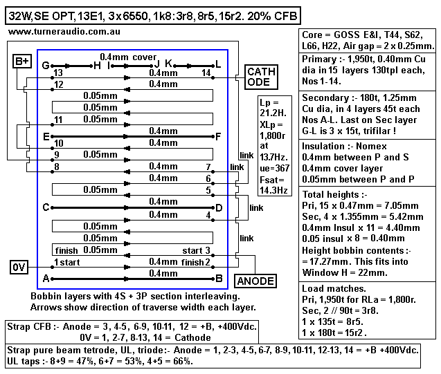
The above OPT has 15 layers of 0.4mm primary wire which allows
Iadc up to 0.25Adc where max
idc current density = 2A / sq.mm.
3 of the 15 primary layers may be used for a CFB winding. You may
expect to need max Vac to g1
= 75Vrms for Va = 190Vrms and Vk = 46Vrms. The 13E1 will operate
with open loop gain similar to
20% UL, but effect of 20% CFB gives quite enough NFB to reduce
effective Ra to less than triode
connection.
3 x KT88 or 6550 could be used with RLa for each then being 5k4,
and I suspect outcome would
be quite excellent compared to a single 13E1.
The single 13E1 with CFB using Eg2 much lower than Ea can have
idle Pda up to about 75W and 46%
anode efficiency yields 34.5W at anode, and if OPT loss = 10%,
expect 31W at speaker terminals.
------------------------------------------------------------------------------------------------------
For tyhe 2008 version od SE32 with 13E1, I placed the PT away from
the OPT and used best core
positions to prevent any significant stray magnetic coupling. The
local CFB and global NFB reduces
whatever small amount of stray magnetic coupling exists. Use of
mild steel boxes to pot the OPT
and PT separately definitely reduce any possibility of magnetic
coupling. The measured THD of the
completed SE32 was very much like the results I obtained with the
SE35, and well below the THD
for SEUL22. The reasons for low THD in 2008 and 2012 versions of
SE32 and SE35 is due to
significant but naturally unforced 2H distortion cancellation
between the driver stage and output stage.
So there is little point to me publishing the THD graphs I
obtained for the SE32, and THD for SE32
and SE35 is similar to good PP amps which usually have much lower
THD than most SE amps.
If there is local CFB in the SE output stage in class A, most
distortion reduction is done in the output
stage, so the error correction signal being amplified by input and
driver stages is very low, so the IMD
otherwise generated by having only GNFB is much reduced.
To avoid the input and driver stages contributing much THD to the
total, the input stage should be a
paralleled twin triode, and can be high µ such as 6SL7, or similar
but smaller 12AY7, or a 12AT7.
I found EL34 to work very well as a triode driver tube and it has
gain 8.7 in schematic above, and it
easily generates the maximum 130Vrms for output stage with 33%
CFB.
But where CFB = 20%, then max Va from driver = 75Vrms, and
although EL34 is excellent, EL84
will work just fine.
Everyone should know all triodes have inbuilt and unavoidable
natural internal electrostatic shunt feedback.
The amount of applied NFB within any triode varies with its gain
and is maximum where triode gain
= triode amplification factor, µ. This can only occur where the
Iac change = 0.0ma, even where the Vac
may be quite high, and a typical SE EL34 set up in triode mode
with a CCS anode load may produce
100Vrms with THD < 1%, or 0.1% at 10Vrms, and this level of
linearity without external loops of NFB
make triodes the the most naturally linear device in the universe.
When operated with some external loop
FB from resistance network or transformer windings, linearity just
gets better. There is plenty of electrostatic
shunt NFB in the input and driver triodes of the SE32 because
their gain is high due to high anode load
values so that gain approaches µ.
Therefore the SE32 will work well without the global NFB if it is
really not wanted, especially where the
speaker load = 8r0 and OPT set for 3r8 load. The damping factor
would be fine without the global NFB
and THD low enough, and sensitivity would increase so that
clipping level needs only 0.32Vrms input.
In SE32 there is only 9dB of global NFB, a tiny amount compared to
the typical 60dB around a typical
solid state amp. The numerical difference is between 3 times to
1,000 times.
If ever anyone were to try to use the 13EI ( or 3 x 6550 ) in pure
beam tetrode without any FB but with
the above dc operation and anode loading, the THD at onset of
clipping may reach 10%.
Alll beam tetrodes and pentodes are like this. 13EI open loop gain
would be maybe 40 though, so there is
lots of gain that can be easily be reduced with linear external
NFB networks of resistance or transformer
windings. The linear CFB path around the CFB stage is more linear
than the internal NFB within a triode
which obeys rate of Iac change proportional Vac x cube root of a
constant squared, and triodes only really
become very linear when there is minimal Ia change. But in a power
output tube a lot of Ia change must
occur because there is real work to be done at a speaker. So a
beam tetrode or pentode makes sense,
and their gain allows external linear NFB loops, and it is easily
driven by a triode which makes high Vac
but has low Iac. As long as the driver tube doesn't go anywhere
near clipping, the total outcome will
produce low distortion. I would never intend using more than 33%
CFB because as the % increases, the
driver THD can become high, and driver begins to contribute more
THD to output than the output stage.
Those wanting to use all 9 pin mini tubes instead of octals for
the driver amp should consider the input with
a parallel 6CG7 and 3 parallel EL84 for driver as seen at Deep Space 845.
The 13E1 cathode needs over 30W of heating. This radiates heat to
anode. The anode can have up to
70W idle Pda so that the heat radiating through glass is a total
of 100W. The 13E1 data give Pda max
= 90W but never ever idle the rube at Pda = 90W becase total heat
= 120W and I found anodes glow
cherry red at Pda 90W. In a PP amp with idle Pda = 20W, allowing
max Pda to to reach 90W with Vac
operation is OK because where music peaks are just beginning to
clip, average output Po = 1/10 of
rated maximum possible with a sine wave.
But an SE tube works hard with Pda at 70W if 32W of pure class A
is wanted. I fitted two 13E1
in a pair of SE amps in 1997 and after an estimated 7,000 hours
they still measured low THD gave full Po
like new tubes. They did develop some positive idle Vdc at their
grids which indicated there were some
gas molecules inside the tube and the gettering was not able to
absorb them all. The use of low value grid
biasing resistors not exceeding 47k does tend to prevent the
positive grid current at idle from going too
high, thus turning on the tube which makes it hotter, thus
generating even more positive Vdc at grids.
For the SE32 the stability depended on gain shelving networks
between V1 and V2, so networks are needed
for LF stability with C9+R8, and HF stability with C7+R9, C10, and
Zobel at output with C16+R24.
This all worked with the OPT I used, but it will NOT work with a
different OPT.
Fig 3. PSU for 2008 SE32.
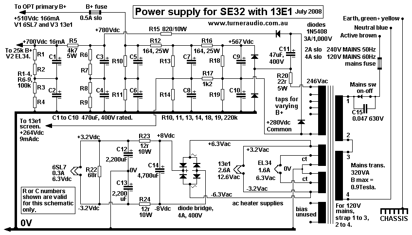
In Fig 3 above, there is a total of 4,700uF for the main 500V B+
supply filtering.
There are no filter chokes, and they are not needed in this case
if there are enough R+C filter
networks in series. The R values can be low, so heat in R is kept
fairly low, and ripple Vac at OPT
B+ connection = 2.8mV. However, R12 and R16 were mounted on a heat
sink to keep their temp
low because they each dissipate 4.5W. Each of R12 and R16 are 5 x
820 x 10W in parallel.
The +780Vdc at the top of C3 is developed by means of a 1/2 wave
voltage doubler working from
the +500V main doubler rectifier for the anode supply current. The
+780V is made by the doubler
formed with C11, and two 1N5408, and feeds C3 through R15, and
peak charge currents are low,
and don't affect the switching of the anode diodes for the main
anode supply.
If anything in the EL34 shorts to 0V, the cheap R will burn open
before the circuit produces smoke
from the PT. A short in the main 515Vdc anode supply will blow the
mains fuse. Active protection
has been fitted to the SE32 circuit to guard against excessive Ia
in 13EI, but has not been drawn up
yet.
It has a simple RC filter using 4.7k from the cathode to a 470uF
cap to reduce the ac voltage but
allow the Vdc at the cathode to be divided down further by a
resistance network and applied to a
C106D sensitive gate SCR. If the cathode Vdc rises to 50Vdc, Idc
in the tube would be 217mA,
and Ea would drop by about 25Vdc, making Pda = about 93Watts, and
the tube would show
some red and be over stressed, but able to cope for a short time.
At Vdc at cathode = 50V,
the SCR is arranged to turn on, causing a relay to open in the HT
winding on the PT so that the
whole anode supply is turned right off, and no damage is
sustained. With such a small Ia change
involved between correct operation and a fault condition, active
protection which has precision which
ordinary fuses cannot provide. Owners are notorious for fitting
the wrong value of fuse after a fuse
blows, and therefore causing much more expensive damage. My
protect circuits can be triggered if
there is a shorted speaker load connected, or if bias failure or
tube failure from any reason occurs,
and the amp may be re-set by turning off, then back on. Repeating
fault conditions mean the amp
needs a visit to a capable technician.
The amps now have a blue "on" LED, and a red LED turns on when a
fault occurs. The 6SL7 has
a dc supply to its heater as shown to minimize its hum. Those
wanting a similar gain and Ra and
wonderful sound and less hum but from a 9 pin tube could use a
12AY7, or 12AT7.
To
SE32, 2012
version
SEUL25, 1997
power amps directory
Index page