Deep Space 845se55 July 2008
Last
edited November 2016.
Some minor comments have been clarified.
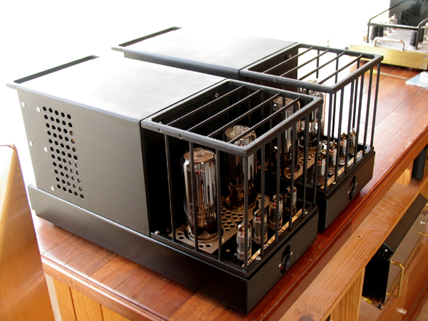
Photo 1, The two 55W amps on my bench.
After a few months of research and development, I completed
construction of a pair of 55W
class A1 monoblocs each using a pair of paralleled 845 triodes for
single ended operation.
These amps were a very difficult handcrafting challenge. I'd like
to think my discerning customer
who waited months will never find any better sounding amplifiers
with such natural clarity
and fidelity. During tests one evening a friend and I were reduced
to tears with some good
recordings. Only the best audio gear achieves a real emotional
impact similar to well performed
live unamplified music which has always been my “gold standard”
for audio quality.
The amps also have excellent technical performance with wide
bandwidth, low distortion,
low noise, and excellent damping factor.
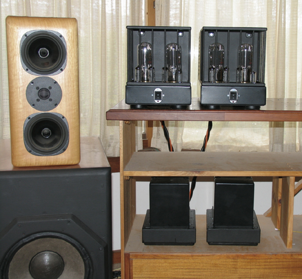
Photo 2.
The first prototype monobloc had all the power supply components
and audio amp
components on the one chassis. But total chassis weight reached
42Kg, and it became
too difficult to move easily, and parts had to be crammed together
too tightly to allow
low chassis temperatures.
So I adopted the same principles I used in my 300W monobloc amps
to have two chassis
per mono channel with power supply on one and audio circuit on the
other, with each
chassis connected with very heavy duty umbilical cabling. This
reduced weight problems
and I could have all hot running resistors clamped inside a
heatsink on one end of the
chassis top instead of having them air cooled under-chassis, thus
the amps stay cool
even on hot summer days. Access to all encased resistors is
possible by unscrewing
the heatsink outer fins.
Each audio amp chassis weighs approximately 30Kg and is 520mm deep
x 230mm wide
x 280mm high.
Each power supply chassis weighs 16Kg and is 280mm deep x 200mm
wide x 250mm high.
Total amplifier weight for two channels is about 92Kg.
Rectifiers are all silicon, and the power supplies always run cool
and can be placed on the floor.
The audio amp chassis can be placed on a bench or equipment stand
above the power
supplies so the front on/off switch can easily be reached, and you
can keep an eye on the tubes.
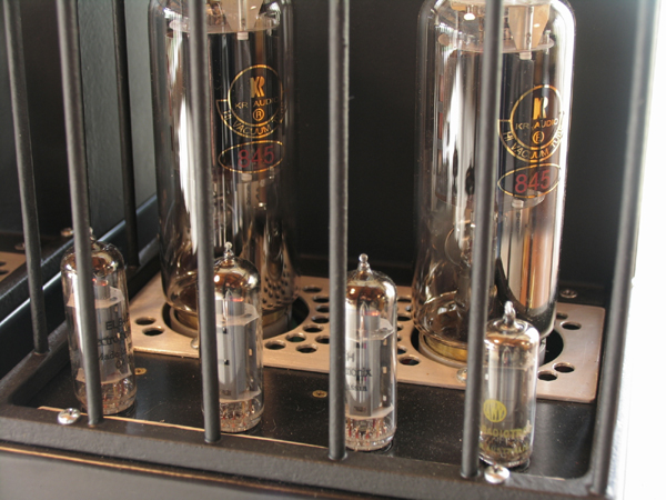
Photo 3.
This shows a close up view with 1 x NOS AWV 6CG7 input,3 x Sovtek
EL84 triode drivers,
and 2 x KR Audio 845 output tubes.
Initial tests were done using "expendable" Chinese made 845
Shuguang type B which sounded
well and measured during many tests.
The amps are made to work with any brand of 845, but the Vac for
cathodes must be changed at
taps on power transformer windings must be changed to suit
Shuguang 845 which require 3.3A
x 10V while KR Audio only need 1A x 10V.
Thus KR tubes run cooler than the Chinese types. The same anode
voltage and anode current
at idle is used, ie, idle Pda = 73W for each 845.
The KR845 may possibly have a very slightly more detailed sound
than the cheapest type B
Shuguang Chinese 845, which I think is the best Chinese 845.
Neither my customer or myself
could hear any difference between KR or Shuguang. The KR tubes
certainly look better made
than the Chinese 845 which are a very close copy of the original
RCA 845 and other old ancient
brands. I did have a customer who bought a quad of Shanling 845
for his Ming Da amps, see
Ming-Da-PP-845-reformed.html
All 4 Shanling malfunctioned with arcing over internally with Ea
more than 500Vdc. The owner
could never get a refund for these overpriced and poorly made 845.
But he has has Shuguang
now for thousands of happy hours.
Both Shuguang and KR 845 had very similarly low distortion levels,
and both adjusted themselves
in my auto biasing circuit with the same biasing Vdc and bias Idc.
Both gave the same power
outputs with the same circuit.
The PSU for each channel produces two 10Vdc supplied for each 845
cathode with choke input
type filters, L + C, and there are 3 taps on two 13Vac windings on
PT so the cathode Vdc
can be finely adjusted for the correct level by choice of taps.
The highest current ever likely for
any 845 is 3.3A for the highest Vac tap is used. The KR may use
the lowest voltage tap for the
lower Idc at cathodes.
RCA or other brands of NOS are so rare now that it’s pointless
trying to find any. Because the
KR tubes use 20W less to heat their cathodes, they could be idled
at Pda = 100W. But the KR 845
are more than 3 times the price of the Chinese types so I have set
up the KR to run at about 75W
at idle to ensure long tube life. See the notes about the
operating conditions below.
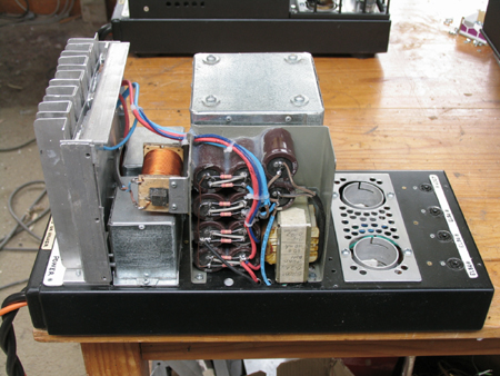
Photo 4.
The amp has its top cover removed in my workshop. You can see the
hand made heatsink to
the left which encloses all the main hot running resistors. Moving
right, the bar cored choke
aka solenoid is for CLC filter for the dc power applied to all
input and driver tubes. Under the
solenoid are two potted E&I chokes for the two choke input dc
cathode heating in each 845.
In the center towards rear is a large potted output transformer
with 72mm stack of 51mm
GOSS E&I lams.
At center front I have an Al channel with some of the 470uF filter
caps in main anode supply
rails and a 60H choke for 36mA dc anode supply to the 3 x EL84
triodes working in parallel.
The 845 'Johnson' tube sockets are recessed to reduce amp height.
4 McMurdo 9 pin sockets are at left end for smaller tubes. White
labels with black lettering
is used to indicate tube type & position to avoid people
swearing and cursing because they
cannot read tiny lettering in the gloom of a listening room.
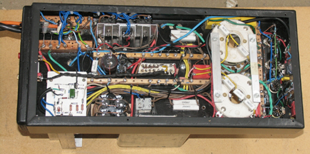
Photo 5.
"Beneath the bonnet"of each audio amp chassis, top left, you can
see the entry and
terminations of the incoming umbilical cables. Towards the right
is a heatsink for three
diode bridges for dc heater supplies, then rail discharge
resistances, then underside of
Johnson tube sockets, and far right you see the compact wiring of
the 4 tube sockets for
input and driver stages. At bottom left is the active protection
board to shut down the amp
if an output tube draws excessive anode current, ie, malfunctions.
Towards the right there
is 60,000 uF in four caps for 845 heater filtering, then rail
discharge resistances.
All wiring is genuine point to point wiring with mainly hardwood
terminal strips well sealed
with varnish. Hookup wire has 1mm thick PVC insulation and is
multi strand copper chosen
for very long term reliability and with very generous current
ratings and much with an
additional shrink wrap layer of insulation added where voltages in
wires are over plus or
minus 600Vdc relative to 0V.
Right in the middle are two rows of terminals which allow a tech
to reconfigure the output
transformer secondary to suit loudspeakers of either 3-6 ohms or
6-or-more-ohms.
Speakers above 6 ohms may be used with the terminations set for
3-6, given excellent
fidelity but reduced power ceiling. 95% of listeners would find
the 3-6 load match to be
excellent for any kind of speaker ever made, as long as 25W was
enough power required.
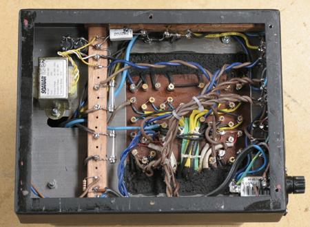
Photo 6.
Here is the under chassis view of each power supply with its
bottom cover removed.
There is a small 5VA auxiliary mains transformer, top LHS. This
supplies 12Vdc power to the
active protection and dc turn on/off circuit. The power
transformer has a board on the RHS
with 48 terminals for taps and ends of windings.
The range of voltages available allow for the use of many
different output tubes and
configurations in future if 845 become scarce or unavailable.
Suitable alternative tubes
are 4 x KT90 in parallel SE with 25% CFB, using the same output
transformer but with
a different winding arrangement on the primary.
Or two x 13E1 can be used. So if ever there are no 845, the amps
can be altered by a
an extremely well skilled tube technician, and sonic purity and
great sound can be maintained
without compromise.
Instead of recycling the amps at the scrap metal dealer, if all
the transformers remain intact
the amps could be re-built into something else, and even a six
pack of EL34, 6L6GC, 5881
could be used.
It is 2016 as I edit this. I definitely will never again be the
available and highly skilled
tradesmen - too many health issues.
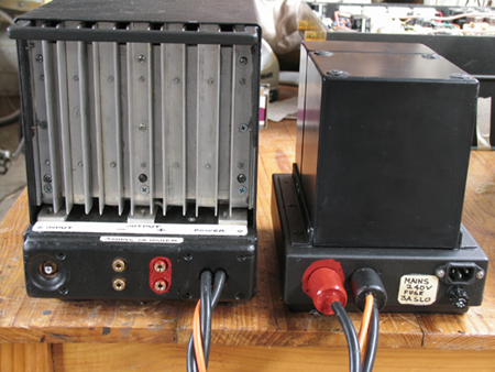
Photo 7.
This workshop picture shows the rear of an audio chassis (left)
beside its power supply (right).
It would be difficult to make a mistake with the umbilical cable
plugs because one is painted
bright red, and so is its socket. When a very absent minded
audiophile inserts both plugs in
reversed and wrong sockets, the amp cannot be turned on and no
damage is sustained when
he turns it on. The choice of pin numbers used for the plugs were
chosen to avoid such an
event, and to keep plug pins with 600Vdc potential difference well
separated.
On the amp chassis there is provision for bi-wiring or having two
speakers into the 4mm bind
posts which are glued into a plywood block to protect them from
breakage, and to ensure
that connections to speakers are only possible with leads that
have 4mm banana plugs.
In other words, the binding posts function as recessed 4mm banana
plug sockets.
Normal binding posts which rely on a wire poked through a hole in
the post and then with a
knob turned tight are an unreliable connection because they
inevitably become loose and
intermittent, and few high-end cables can be used this way. Most
hi-end cables have gold
plated 4mm banana plugs. Way back in 1952, Quad thought the same
way in about 1952
with their Quad-II amps, ( they sold over 100,000 ).
The only problem with 4mm banana plugs is the risk that someone
yanks cable or treads on
cable entry with amps in the floor, and thus breaks off the plug
end, which remains lodged in
the socket. I once did this on a speaker terminal. I used a 1mm
drill to put a hole in plug end
and then used a wire to haul out the plug end. This is highly
skilled work, and I know of
nobody else who capable and who would not leave a messed up
socket.
People who build new amps or speakers should make sure the banana
sockets are mounted
in a small removable panel which is easily unscrewed to allow a
inside access to the 4mm
bore to allow a plug end to be pushed out. I could not find any
such suitable sockets.
The ideal banana socket has not become available anywhere yet.
Input socket is a Cardas RCA input for a single ended input only,
shown recessed on the left.
On the amp rear side to the right, the umbilical cables emerge and
are soldered into the amp to
avoid connection confusion, and the problem of having too many
plug and socket connections.
Cable length is 1.5metres, so the power supplies may sit on the
floor, out of sight, out of mind,
and away from any other gear, while the audio chassis may be on a
bench 900mm high to allow
easy access to the on-off switch, and to keep an eye on the tubes.
The rocker type on-off switch is recessed to avoid damage, and it
switches low voltage 12Vdc.
The actual mains switching is done with relays within the power
supply. Thus 240V mains
wiring is not brought into the audio amp chassis and so there no
diode switching noise spikes
or hums from where the on-off switch is so closely situated to the
audio input circuits.
Schematics.
I have published all my schematics and all amp details for free. I
am not afraid of anyone
stealing or copying anything I have done. But nobody is going to
copy what I have done and
make a profit because these amps will have a cost of production
far in excess of most cheap
nasty toy like amplifiers which one can see advertised around the
Internet.
The few other manufacturers who supply similar power levels of
Single Ended triodes dare not
publish the full details of their amps lest the secrets about
their shortcomings become obvious
to the hordes of people who would publish criticisms and reduce
sales and profits.
Many manufacturers do not want you to know how they managed to get
the cost of production
to down to a very tiny fraction of what they want you to pay.
Nobody could faithfully copy my designs and be able to make a
profit without employing an
arsole to remove the quality to cheapen the cost of production -
thus stealing and ruining
your music, and lessening the amp reliability, so it barely
reaches a typical 90 day warranty
period before the amp troubles begin. I know it happens; I
repaired piles of overpriced junk.
I have never obtained a favorable review from magazines such as
Stereophile after paying the
huge sums. In 2016, I wonder how much relevance Stereophile has
now; I would imagine it
has been severely undermined by the chatter on the Internet.
Nobody really knows who makes
a good amp now - unless proven otherwise - by extensive
revelations of all details, like you see
here.
But most ppl buying hi-end audio do not understand a word I type.
So for them, buying hi-fi
gear is a gamble. Maybe it sounds OK, maybe it lasts, but whatever
happens, they can
buy another solution later if it does not work out. I've known
audiophiles to become tired of
what they bought, and need to replace everything yearly - they
hunt continuously for the
ultimate, always conning themselves they are going to get
something slightly better because
it really is more "ultimate" than the last six purchases. There is
a lot of complex psychology
going on in minds of those who have the money to consume hi-fi
gear with relentless passion.
I am not much surprised by their appalling levels of musical
appreciation. But part of being
human is to consume, and to consume at great expense, and to
excess, and there's never
goods and services and never enough dough to get it all, and
there's never any serious
attention given to frugality, which is hugely
boring.
Warning. There are
high voltage potential differences of up to 2,000V
within each
amplifier when operational.
Only trained and experienced technicians should
attempt to examine the working
circuits or build the circuits shown in the
schematics.
SHEET 1. SE55 input and driver stages.
Input signals enter the input V1 6CG7 with both halves paralleled.
There is a high pass CR
input filter with C1-R1 to give a pole at 5Hz. This keeps out dc
in sources and extremely low
frequency signals. The MJE350 transistor might seem to be quite
out of place in a tube circuit,
but it acts as a passive component which supplies V1 anodes with a
non changing current or
what is called a constant current source, CCS.
The CCS acts in a manner identical to an equivalent resistance of
several megohms to an
imaginary supply voltage of thousands of volts. Such a resistance
and supply are utterly
impractical, and not needed. It would have been possible to use a
pentode to perform the
same function as the MJE350, but in this case the MJE performs
better than any tube.
Because the effective real dynamic collector resistance is so
high, it cannot impart any sonic
signature in the signal path, apart from allowing V1 to operate
with less THD than if it had a
"normal" resistance between the B+and anode.
Best sound with triodes is obtained when the least change of anode
current occurs.
So with the MJE350, V1 anode load is effectively the following
capacitor coupled biasing
resistance R11, 180k. The Ra of V1 is about 5k0, and RLa is 36
times greater than Ra, and
when triodes are loaded with RLa > 20Ra, they give the best
sound, and the lowest possible
distortion measurements. If you were to replace the CCS with a
simple resistance of about 39k,
THD/IMD would increase 3 times. The THD of V1 is mainly all 2H,
but it will add to that of the
output stage because both V1 and output stages have the same phase
of the 2H, so to
minimize overall THD, the CCS transistor helps to lower overall
distortion. The high RLa
value of V1 maximizes its voltage gain, which cannot exceed the µ
of the triode.
6CG7 has same electronic parameters of 6SN7, with µ = 20, Ra =
10k, gm = 2mA/V. Full
explanations about mysterious inner workings of a triode may be
found at my pages
beginning at basic-tube-1.html
Any brand of 6CG7 may used. My favorites were once Telefunken or
Siemans NOS made in
Germany. I've never known anyone who can tell the difference
between the German 6CG7 and
NOS versions made in Australia by AWV before 1965. Genuine NOS
German 6CG7 are hard to
find and ruinously expensive. The expense is because they have
become rare, and not only
because they have a good sound reputation.
I suggest the Australian made AWV are very "fine wines" indeed,
and those who insist the
German triodes are better might do because they have paid so much.
In a blind A-B comparison
they might be surprised.
For greater input sensitivity, 6922/6DJ8 could be used for V1. One
would have to use 2k7 R4 grid
resistors at each grid because the 6DJ8/6922 does tend to
oscillate at around 200MHz if you
parallel the two halves without using two separate series grid R
"stoppers". The cathode biasing
resistor, R5, would need to be reduced in value until Ea measured
about +120Vdc.
The 6CG7 is an evolution of the famous octal based 6SN7. Oz made
samples often used exactly
the same anode, grid and cathode structures but just mounted
slightly closer, and a slightly lower
anode Pda rating given for the smaller 9 pin size. There was often
a screen also fitted between
each anode taken to pin 9 and 0V. The 6CG7 technical character is
identical to 6SN7 and it
ensures the audio signal is amplified very linearly, while
maintaining excellent musicality, micro
detail and warmth, transparency etc that one enjoys with the best
tubes when set as I show.
German 6CG7 and some Japanese 6CG7 were made with smaller anodes
than Australian
made 6CG7 or 6SN7, and some had slightly higher µ 21, or 22. But
anything labelled 6CG7
( or 6FQ7 ) will function well in a circuit designed for 6CG7.
8dB of global NFB is applied from the output transformer through
R3&C2 to the top of R6.
C6, C7, R8, and R11 form a LF gain stepping network to optimize
the LF stability and fidelity.
V2,3&4 are triode connected EL84, each with individual cathode
biasing. Any brand of EL84
may be used, and you could have 3 different brands together if
need be because they each
have their own cathode biasing network. I've fitted Sovtek which
sound well, and mixing up
brands or using 3 x NOS EL84 may or may not make a change.
Three EL84 are used to produce what becomes ONE super triode with
Ra = 700r, µ = 20
and gm = 28.6mA/V. As shown, it makes can easily make a maximum of
164Vrms of signal
Vac with less than 2% THD, and with good gain, and wide
bandwidth.
The use of L1 60H choke plus 7k0 to supply Ia = 36mAdc to the 3 x
EL84 provides a high
ac impedance anode supply load which dissipates an extremely small
amount of ac power,
so hence the excellent linearity, because like V1, RLa is many
times Ra, and RLa approaches
a CCS. L1 has XL = 18k at 50Hz, and at 1kHz XL > 200k. The 7k0
isolates the shunt C and
shunt L of choke, so minimum RLa for EL84 is 7k0. I've always
found the L + R method of
supplying Idc to driver stage anodes in SE and PP amps has given
the best sounding
dynamics, ie, better hi-fi. The capacitor coupled load for EL84 is
the biasing R for following
845, R28&R29 of 23.5k. The use of high Z dc carrying RLa
allows the following biasing R to
be low, to more effectively keep output tubes at the wanted bias
Vdc.
At 50Hz, the EL84 triode RLa = 20k of L1+7k0, plus 23k5 in
parallel for a total of about 16k0.
RLa > 23 Ra. But above 100Hz, RLa = 28 Ra. This ensures minimal
THD&IMD and maximum
fidelity.
There is shunt regulation for V1 anode supply using zener diodes. This assists LF stability.
Any noise in the zeners is filtered by R21 and C9. The CCS MJE350
in series with low Ra
of V1 forms an R divider to prevent any rail noise entering V1
anode circuit.
SHEET 2. Output stage 2 x 845.
Sheet 2 shows each 845 is set up in conditions as follows :-
Ea = +1,060Vdc, Ia = 70mA,
cathode bias voltage = 150Vdc, RLa per tube = 12k0, and so for
both 845, the OPT load is 6k0.
The maximum drive voltage to 845 grids for clipping is up to
approximately 110Vrms containing
1.4% 2H from the driver stage. The driver stage anodes applies the
drive voltage to the network
of C16,17,18 and R23, 24, 25, 28. This network transfers the
signal safely from the EL84 anodes
at +310Vdc to the 845 grids at -600Vdc.
Coupling caps are 2.2uF each and each rated at 1,000Vdc and the LF
pole is at 9Hz.
The 845 anode current is supplied from two rails, one at +600Vdc,
and the other at -624Vdc.
This unusual arrangement reduces the likelihood of arcing within
the OPT between anode
windings and earth potential secondary windings. The filtering of
the two rails is by C-LR-C-R-C
set up to give a damped LF pole. Many tests were done to ensure
the continual mains voltage
level changes and LF switching noise caused by other users
connected to the mains supply
does not create LF resonance signal which then appears between
grid and cathode of the
output tubes, and therefore does not appear in the output in
excess of 0.5mV, even if mains
noise level change is very bad. The overall noise
performance despite the twin rail use is
extremely good. Despite so little global NFB these amps were the
quietest tube amps I have
ever built.
Two supplies of 10Vdc are applied to 845 cathodes xx and yy so
that rectifier ripple Vac > 20mV
and is balanced by R30&31, 32&33.
SHEET 3. Cathode heating with dc for all tubes.
Sheet 3 shows the three simple heater dc supplies used for ALL
tubes within the amp.
The L3, L4 chokes used in the choke input dc supplies for the 845
cathodes are
potted and do not cause any magnetic interference in the potted
OPT on the same chassis.
L2 is a solenoid type of choke in a CLC filter, so the Vac across
the choke is tiny, and thus
its change in magnetic field is negligible, so potting was not
needed.
SHEET 4. Main power supply for 1 channel.
Sheet 4 shows the main power supply chassis has all the above
within to generate the
positive and negative B+ and B- Vdc rails for the 845 and other
tubes. There is also a stand
alone auxiliary +12Vdc rail to supply power for the on-off Relay 1
and for protection circuits.
The use of low Vdc rail for switching mains avoids having any
mains wiring within the audio
chassis. And if any umbilical cable is not plugged in correctly,
the amp cannot be turned on.
Power for DC heating all cathodes has Vac transferred from PT via
umbilical cables and
rectifying Vac is cone on the audio chassis. This avoids high
current DC power transfer by
cables. The noise of diode rectifiers operating to give low Vdc
with low noise does not increase
amp noise. And there was more available chassis space on amp
chassis, and not enough on
PSU chassis. See notes below sheet 6 about power transformer and
iron core component
replacement.
A large number of rail voltage arrangements are possible.
FUSES.
Caution!
The amp must be turned off and mains cables removed from wall
socket before
change of any fuse. Wait 10 minutes before changing any fuse
!!!!!!!!!!!!!!!!!!!!!!!!!!
Fuses or fuse wire links for all windings are as follows:-
F1, Mains input, for 220V,
230V, 240V, 3A slow blow, type 3AG, and accessible at rear of
PSU by owner. For 100V, 110V, 120V operation, mains fuse is 6A
slow blow type 3AG.
All fuses below may only be replaced by a technically trained
person.
F2, F3, F4. Three fuse wire
links rated for 10A soldered into the underside of the psu
chassis and covered with black polyester sleeving for 2 x 845 ac
cathode heater windings
and one other cathode heater winding for 3 x EL84, and 1 x 6CG7.
F5, F6. Two x
3A slow blow, 3AG, soldered into place under psu chassis for the
two main
HT rails of +660Vdc and -640Vdc, derived from voltage doubler
rectifiers.
R58 Provides some protection for the auxiliary small power
transformer under the psu chassis.
This 1W resistor will burn out if the auxiliary transformer is
shorted.
845 Anode fuses, There are two 0.5A slow blow 3AG fuses
soldered between the
bottom of R36 and each 845 anode in case the anode current exceeds
0.6Adc.
SHEET 5. Active protection against excessive Idc in 845.
Sheet 5 shows active protection against lounge-room disasters
including audio silence, clouds
of smoke, and a terrible toxic smell. Tubes don't last forever,
and can sometimes fail randomly
before their expected lifetime.
Often such failures are provoked by a careless owner connecting a
faulty speaker, or allowing
speaker cables to be shorted. In the unavoidable and inevitable
eventual malfunction of one
or more 845 in what is called a "bias failure" event, you want the
amp to TURN OFF as soon
as the tube overheats. The tube may be OK, but there may be some
other circuit fault.
845 are expensive, so they need protection.
I have had to repair very many "good" hi-end brand amplifiers that
gave a lot of trouble due to
poor design, or through mishap caused by owners, or malfunctioning
speakers etc, etc, etc.
Often I have had to repair amps where the fuses were the last
things to blow. On some amps
there was evidence of a small fire which damaged parts of wiring
and circuit boards.
To avoid smoke in the listening lounge room, and collateral damage
to other parts within the amp,
most amp makers do fit a couple of fuses, but they are often
almost useless.
They don't always blow when one wants them to, and owners are
notorious for replacing them
with something convenient like aluminium foil from the kitchen or
using a 2A fuse instead of
0.2A which encourages a faulty amp to burn the house down.
Active protection is needed to automatically stop the smoke and
damage and to tell an owner
when something is wrong, and if possible to shut down the amp and
prevent fuses blowing.
Nevertheless, I have a fair number of fuses fitted in these amps
and apart from the mains fuse
they are all soldered into place because fuse holders are
notorious for not holding a fuse firmly
and becoming loose over time, and thus becoming intermittent
especially with dc flow.
Fitting new soldered-in fuses is a painful exercise requiring a
tech with a soldering iron.
The most likely problem in any tube power amp is the sudden or
gradual unwanted increase in
the idling dc current flow in each output tube. This current is
usually called the anode bias current,
and it is controlled by the voltage between the grid and cathode.
But a tube can change its
character as it ages or during some trauma such as caused by a
shorted speaker cable, and
despite the biasing voltage Vg-k, the bias current may increase to
many times the idle value,
with dire results if not dealt with ASAP, within seconds.
The above simple circuitry will shut down the amp in 90% of bias
failure or tube failure cases,
and if the failure was caused by some temporary fault, it may be
easily reset to go again simply
by switching off, then on again as explained in the text in the
schematic above.
Under normal operation, the 845 anode current is around 70mAdc at
idle. This generates 150V
across cathode R34&R35. Should the anode current ever rise to
about 102mAdc, there will be a
cathode bias voltage of 225Vdc, which means the Pda will have
risen to about 100W, and although
this is the maximum rated Pda for 845, its plain wrong in these
amps and due to a fault condition.
So to give the fault condition it only takes an Ia increase of
32mAdc, or 45%, and you cannot rely
on fuses to blow with such a small amount of current change, so
active protection is the only reliable
way to prevent Ia rising to perhaps 400mAdc in this amp. 400mAdc
would damage the cathode
bias resistors, and perhaps the OPT primary winding if the
condition lingered for too long, and I
have seen this happen in many amps brought to me for repair.
The protection circuits have utterly no effect on the sound.
SHEET 6. Power transformer details.
Sheet 6.
The power transformer does not run very hot because the turns per
volt ratio gives a B-max of
less than 0.9 Tesla, and wire sizes are generous and rated for no
more than 3A per sq.mm of
copper wire section area. The transformer is neatly layer wound
with layered construction shown
in the drawn section through the winding bobbin.
I gave a two year warranty on amp transformers. But if one were to
fail, and I was not around in
future then there are no standard easily available replacements
for any iron cored wound
components in these amplifiers from any known commercial
transformer winder.
All are custom wound and may have to be ordered as a special order
from perhaps Sowter
Transformers located in the UK. Sowter would be the only
transformer maker I know who could
produce a power transformer to do fairly close to what is done by
my originals. But I doubt they
would like to include the the many taps for alternative tube
usage.
I hate to think what the cost of a replacement PT could be from
Sowter.
Most other commercial transformer winders HATE TAPS anywhere; they
just cannot cope with
the levels of complexity and thought I put into all my work.
If one PT were to fail, it would be possible to build two power
supplies on ONE new chassis using
a larger single PT rated at 1.2KVA, and re-use many parts you see
here. This sounds like a huge
amount of work, and it sure is, but it means the single
transformer would have the same core
lamination tongue size of 51mm, but have a GOSS stack height of
100mm instead of the 72mm
now used. Wire sizes would be thicker, but fewer turns per volt
are used, and it’s no more difficult
to wind than winding a pair of PT with cores now rated at 650W for
cool running.
An alternative is to rebuild the power supply on a new chassis to
allow the use of multiple power
transformers which may need to be sourced from Hammond Engineering
in Canada. In 2016,
I am not sure if there is a reliable supplier of Hammond products
in Australia. The Oz company
evatco.com.au changed hands 2 years ago and I don't hear any good
reports of how it now deals
with mail orders. So if you need a new PT for these kind of amps,
you would have to consider
completely re-designing and re building one big PSU to cater for
both channels. Experts who
specialize in such work have all retired or died, and I've
retired, and will die soon.
I sold the pair of 845 SE55 to a customer in Australia in 2008. I
retired from the amp trade in
2012. Its now 2016, and my customer has not had the amps ever
serviced here so I guess he has
not ever had any need to replace any transformers or other parts
requiring my past expertise.
The OPTs and PTs can be removed from chassis, terminal boards
removed, and sealing layer
of resin and sand concrete seal removed with chisel and hammer.
The remaining loose dry sand
surrounding the transformer can be drained out. The transformer
should be able to be removed
from its pot and thus the pot can be re-used.
To dismantle the wound transformer all bolted angles and bolts are
all removed. The grain
oriented silicon steel core can be salvaged by heating the
transformer in a small wood fire to
burn off plastics and varnish. When cool, the burnt wire is cut
away for re-cycling, and laminations
should all fall easily apart and will be ready for re-use. The
slow heating and slow cooling will NOT
affect the core magnetic properties. A new transformer is then
wound using a new plastic bobbin to
suit a 70mm stack of 51mm tongue laminations so that it will fit
inside the pot. The newly wound
transformer must be varnished while being wound or after with a
soak and bake method.
A new terminal board is made and fitted.
After testing the new transformer it is re-assembled back into its
pot and clean dry sand used
to fill the pot except for the last 15mm. The sand must be
thoroughly vibrated and settled.
Spray-can varnish is applied to the sand surface and next day the
top 15mm of fill is with a 50-50
mix of epoxy (fibreglassing) resin and sand. This seals the pot
and prevents dry sand running out.
The spray varnish prevents liquid resin soaking into dry sand
below. The completed tranny is
re-installed into the chassis and connected up and tested.
This is what is involved with serious repair to these sort pf
amps. I have done this kind of work on
many amps I serviced.
In 2016, I DO NOT know anyone in Australia with sufficient
competence, knowledge and
patience to do such work on transformers.
The gentleman who made the amps has got old, and is now quite a
bit stuffed up from countless
years of toil to please other ppl plus a number of health
problems.
The power transformers and other wound components such as chokes
and OPT have been
designed to run cool, and all windings have fuses, and active
protection is used against output
tube failure. I believe I have done enough to ensure transformers
will survive a long time.
After winding so many power and output transformers and chokes
between 1994 and 2012, not
one has failed, so I have never needed to repair any of my work.
Much time has been spent on making the iron cored items in these
amps.
SHEET 7. OPT for SE55.
Sheet 7. shows the OPT details which was layer wound and varnished
with Wattyl 7008
polyurethane two pack varnish generously applied to windings as
the transformer was wound.
The completed OPT was potted in a zinc plated sheet steel pot and
filled around with dry sand
well compacted with a finishing layer of epoxy-sand concrete.
The output transformer is more difficult to wind than the power
transformer because of the
high number of layer wound turns around a large core with fine
wire only 0.52mm dia.
There is no known ready made replacement type available from any
manufacturer such as
Hammond Engineering. Perhaps Sowter in UK may wind a new OPT, do
not expect them to
adhere to my recipe for an SE OPT for 6k0 : 4.0r or 6.25r. They
just choose something "close"
from their list of hundreds of OPTs wound after WW2. I did once
pursue Brian Sowter to
obtain a quote to wind a replacement OPT for Quad-II amps which
would be much better than
the original, and fit on the original chassis. He would NOT wind
it just how I had it detailed.
When questioned just how he would wind it, so I could compare my
design with his, to see if
better or worse, he refused to ever tell me. His designs were his
trade secrets, and were not
ever to be given to anyone else. And certainly never to some
up-start nobody from Australia
who knew more about how OPTs functioned than he did. This became
obvious during the
emails. The costs were huge to have him do anything.
So, this is why I just could not ever deal with anyone who could
not prove they knew all about
what they were selling, and who could not design any OPT from
scratch without reliance on any
previous records. So many ppl who say they are experts are not
experts.
Ian Sowter, Brian's father, WAS a huge expert and much advanced
the knowledge of audio
transformers well before WW2. Brian probably had so much to occupy
himself with in daily
running of the company that he may have escaped having to ever
proove he knew as much as
his dad, and could design an OPT - until I came along to ask him
questions he could not answer
to my satisfaction.
The dynamic anode resistance Ra of the two 845 in parallel is 1k1
and when this Ra is in parallel
with an anode load of 6,000 ohms, the source resistance = 930r
shunting the primary inductance
of 40H with 150mAdc present. The -3dB response drop at LF and low
levels below Fsat and due
to primary shunting inductance occurs at 4Hz. At 50W output level
the onset of core saturation
occurs just under 20Hz. And at 12.5W, with Va = 1/2 that for 50W,
Fsat = 10Hz.
The RLa of 6k0 = XLp at 24Hz. So when testing the amps with 6k0
anode RLa, the THD at
50W level rapidly increases below 24Hz because the load has become
partly reactive with Lp in
parallel with RLa to give total load impedance = 4.24k. But at
12.5W the THD increase at
LF is very much less.
At 50W, the HF -3dB point is above 30kHz, all with zero global
NFB. Some of the slight sag
in HF is due to the stability network of R37&C23 beginning to
load the amp above 50kHz.
Shunt Capacitance from the primary anode terminal No1 to the
secondary is less than 3,000pF.
Leakage Inductance has slightly less attenuation effect than the
shunt capacitance, and
the resonance between leakage L and Shunt C is above 30kHz.
Primary winding resistance Rwp = 95r for 2,760 P turns, using
0.45mm dia copper wire, about
0.52mm oa dia with enamel. Rwp loss% = 1.56% with RLa = 6k0.
Secondary winding resistance = 0.124r for 5 x 72 turn secs in
parallel, 0.9mm Cu dia wire.
Rws loss% = 3.0% with Sec RL = 4r0.
Sec winding resistance referred to primary = 182r so total Rw =
95r + 182r = 277r.
Total Rw P + S loss% = 100% x 277 / 6,277 = 4.44% with RLa = 6k0.
This result should be equal
to 1.55% + 3.0%, 4.55%, but is obviously not, but the referencing
of Rws to primary assumes
some slight difference in equivalent L+R schematic. The referring
to primary of secondary Rws
is still accurate enough to use. The higher figure of 4.55% is
very good because many SE OPTs
measure with much higher winding losses with 7% to 10% being
common.
Where a speaker is say 6r0, and connected to OPT set for 4r0,
total winding losses reduce to 3.0%.
LOAD MATCHES AVAILABLE.
5 x 72 turn parallel secs give TR = 2760t : 72t = 38.333 :1. ZR =
1,469 : 1. A sec load of 4r0
gives RLa = 5.877k plus Rw 277r = total anode load = 6.154k. Near
enough to 6k0.
All speaker loads above nominal 3r0 Z rating may be used.
4 x 90 turn parallel secs give TR = 30.666. ZR = 940 : 1 so for
sec RL = 6.25r, anode loading
is the same as for 4r0.
All speaker loads above 5r0 may be used.
The current density for all sec winding wire is the same for
5//72r or 4//90t.
The third option is to use 4//72t in series with 2//36t for Ns =
108t.
OPT TR = 25.555 : 1. ZR = 653 : 1, so for same RLa load as before,
Sec RL = 9r0.
This allows all speaker loads above 7r0. The total winding losses
will increase slightly
by maybe 1%, and HF pole may slightly reduce, and the hi-fi
experience will not change.
All speakers including ESL types by Quad such as the ESL57, ESL
63, 989, 2805 should be
tried with the 4r0 setting before committing to the trouble of
changing the setting to a higher one.
Many older high impedance speakers of say 16r0 are much more
sensitive than more modern
types, and therefore require a similar amount of signal voltage as
a modern 4r0 speaker.
The amp current needed for 16r0 is 1/4 of than for 4r0, the RLa
becomes 24k0, and max Po
will be only 15W, but DF and THD are both more than halved, and
sound is unsurpassable.
Most people will never use more peak power above 10W. Average
power is well below this,
often only 0.25W per channel. Because the amp measures so well at
55W, at an average power
of 1W the distortion is well below audibility.
SHEET 8. Choke details SE55.
Sheet 8.
Six chokes per channel are used for filtering and to prevent the
heat losses using alternative
methods of filtering or active regulation. No solid state chip
regulators are used because they become
unreliable when used in circuits with such high voltages lurking
about. There are a few simple zener
diodes for basic shunt regulation, but used so they are under no
heat stress. The main positive and
negative voltage rails of over +600V and below -600V have a
C-LR-C-R-C type of filter. Each C is
formed with 2 x 470uF in series to make 235uF, and total C per
rail = 705uF. There is a resonance
between the 4H choke and following 235uF at 5.2Hz. The added 100r
in series with L reduces the
noise peak at 5.2Hz. The following additional 100r plus 235uF act
to damp the peak in the resonance,
thus making each voltage rail less liable to vary at LF below 10Hz
due to the unavoidable mains
voltage level changes that occur continuously, and typically of
+/- 20mV to +/-200mV.
I have found the steady average value of mains voltage can be from
235Vac on a cold winter evening
to +255Vac on days with little mains load, with 247Vac being most
common here in Canberra.
Many high end brand amps have been designed to run in the USA with
a nominal 110Vrms mains or
220Vrms. Many such amps have fixed bias and tubes run
unnecessarily hot even with the correct
mains voltage present. But here the mains voltage is often 250Vac,
and with fixed bias these amps
often overheat badly when tube Pda rises close to or above the
rated maximum Pda. Jolida and ARC
amps suffer in this manner badly, and need to have alterations
made to their PSU to prevent the B+
from exceeding the capacitor voltage rating and to stop the tubes
exceeding their Pda levels.
Many owners have thanked me for the efforts I have made in this
regard. But in my amps, there are
tapped windings to allow for worst case voltage variations.
The SE55 work just fine where average mains = 245Vac, but will
work fine with mains between
220Vac and 255Vac. The maximum output power will vary between +5%
for higher Mains Vac and
-10% for lower Vac, so between 58W and 52W. It is quite "enough"
power.
SHEET 9. Resistor layout on heatsink.
Sheet 9 shows the arrangement of resistors used within the
aluminium heatsink at the rear end
of the amp chassis. Cheap ceramic bodied wire wound types are used
with their dissipated power
being well below the rating for the resistance chosen. These are
readily and cheaply available
from many suppliers. A total of about 50W is dissipated in the
resistors shown with normal
operation. To keep them all cool and thus more reliable, the
heatsink was built up to enclose the
resistors behind a removable cover fitted with many fins and which
springs tightly against the
enclosed resistors.
Resistors are glued to the 3mm thick aluminium heatsink fixed
plate with Selleys 401 engineering
grade silicone with a temperature rating of 200C. The screwed
cover can be removed by
removing the 9 x 4mm metric machine screws. White heatsink paste
is used between resistors
and the cover. While it is possible than resistors might fail, my
experience tells me it is not likely
that they will fail, unless the current flow is 10 times more than
normal. Wire wound resistors usually
fail by fusing open, and they may be prized off the heatsink with
a chisel, and a new one fitted.
The standard size for 5W and 10W white ceramic boxed R have
section size 10mm x 10mm so
will fit the same space for them.
It is a messy job to replace any resistors, and a tech needs to
know what he is doing, but at least
the resistors are easily accessible once exposed to view. While it
may have been wiser to use
much more expensive aluminium bodied resistors each screwed to a
heatsink, there was no need,
and the method used is entirely adequate, and any fused resistors
are cheap to source and easy
easy to replace.
SHEET 10. Umbilical cable details.
Sheet 10 shows the layout for rugged cables used to get power from
the power supplies to the amp
chassis. When the amp chassis are examined with a copy of the
above, just exactly how everything
is set up becomes less confusing. The octal plugs at the ends of
cables are permanently connected.
All wires are soldered into the hollow pins of the plugs. There is
no access to the wire ends leading
into the hollow pins of the plugs. If a pin is broken off a plug,
the whole plug is made useless.
The only solution is to cut the plug off, and rewire a new octal
plug onto the lead as shown above.
A cheap type of octal plug from RS components could be used to
make a new plug.
The original plugs were made using only the bottom base from an 8
pin octal tube. This had the sides
ground off so the base fits neatly inside a 30mm long piece of PVC
electrical wiring conduit tubing with
about 25mm internal dia.
The central keying spigot of the plug has a 4mm threaded rod
inserted to reinforce the spigot which
otherwise will all too easily be broken off accidentally by a
careless owner, leaving no way to correctly
locate the plug into the socket at the power supply, and therefore
promoting many bad tempered
experiences while trying to make the amplifiers work. Both plugs
MUST be plugged in correctly for
the amp to be able to be turned on.
There are some inbuilt safety features of the umbilical cables.
While plugged in there is little danger. The danger from a shock
is no worse than any normal 240V
wall socket plug used for many other household appliances. It is
impossible to turn on the amps with
only one octal plug plugged in, or with plugs reversed, i.e, and
red into black socket, black into red
socket.
However, if somebody were to wrench one of the power supply cables
from the power supply while
the amps are turned on, the amps will turn off immediately. If any
person were to immediately grab
the pins of the plugs after removing them, then they would be
connected to the live stored voltages
within capacitors in the amplifier chassis. Diodes have been
placed to prevent the flow of current
from these capacitors, see D1, D2, sheet 2, thus preventing a
shock. The 845 cathode heater
supplies are biased at the cathode voltage of -450V but at turn
off there is a relay to reduce this
voltage to less than 40V within less than 0.5 seconds, so it would
be very unlikely to experience
any kind of accidental shock unless one tried desperately to do
so.
It would be unwise to allow a pet dog to chew on cables. Most
animals will get a surly warning from
Unkel Sparks as they chew, and and learn to leave them alone. The
cabling used is particularly rugged
industrial grade cabling with thicker PVC insulation than used for
high power 240Vac rated cables.
Indeed the cabling is normally used for 415Vac 3 phase high power
supplied to industrial electric
motors. Peak Vac with back emf in such cables could be 1,000V. The
highest voltages are carried
in the two thick black cables while very low voltages are carried
by the orange cable.
For all things you cherish, my practiced care was my best
insurance. It was impossible easily build
such amplifiers to be fully child safe. Little hands will reach to
touch anything. However, the tube
heat will cause pain before a burn is sustained, and children soon
learn the danger of anything hot.
If there is any doubt, supervise children, if not, make sure the
amps are secured so a bench, and
additional mesh screens made and fixed to prevent child access or
amp movement. When I was
a child, I don't recall I cause grief to my parents by upsetting
the many dangerous things in our
lounge-room. When I did eventually become curious about hot vacuum
tubes in open-backed
radio sets, I was about 15 years old, not 15 months old.
Place power supplies on the floor behind the amps. Cables and
speakers should not pose a risk
of being tripped over by passing traffic. These amps have been
made fairly ruggedly with steel
chassis. All tube amps don't like being dropped, or pulled off a
bench by a trip on a cable.
Metalwork can easily be damaged in falls because of the weight.
Amps should never be moved
while turned on. The umbilical cables should be unplugged, and
coiled up and tied up to the rear
carry handle on the amps. Never ever let cables trail along on the
floor to get under your feet, or
catch on anything.
--------------------------------------------------------------------------------------------------
There was a "Sheet 11" which showed a graph of THD Vs Power output
but this has become
corrupted and I did not have any back up copy.
So what is the THD, Total Harmonic Distortion?
All amplifiers and many transducers add noise and harmonic
products to any signal flow.
If you have a single triode making 10Vrms of 1kHz, the triode may
add 0.1Vrms of 2kHz which is
1% 2H. There may 0.025Vrms of 3H, = 0.25%, and similarly, perhaps
0.025% of 4H.
Many H products are generated, but the 2H will be the largest H
with a triode.The total value of all
harmonics is calculated =
THD = square root ( 2H squared + 3H squared + 4H
squared.........).
For the sample above, THD % = sq.rt ( 1squared + 0.25 squared +
0.25 squared ) = 1.125%.
Where 2H much exceeds all other H, by at least 5 times, as is
typical for a triode at low levels,
we may ignore all high number H and just concentrate on 2H.
All THD is a devil in the music. But every music tone has many H
products. If the levels of these
H are slightly altered by 1%, nobody notices. But where there is a
pure tone, adding 1% of 3H
may be audible. The real horrible work by the THD devil is to
produce Intermodulation Distortion,
IMD.
The THD figure is really a description of the transfer function of
the amp. Let us assume an SE
triode amp makes 5% 2H near clipping with 80Hz. It means that the
tube gm and gain varies for
each 1/2 sine wave. If a second signal tone of 5kHz is introduced
at input, and at 1/4 of the level
of the 80kHz, the amplitude of 5kHz will be varied; it is
amplitude modulated and at amp output
we will find the following H products :-
80Hz, 160Hz, 5kHz, 4.92kHz, 5.08kHz, 10kHz. The 4.62kHz and
5.08kHz are not harmonious
with fundamental tones 80Hz or 5kHz. It is the IMD which is the
devil's work on fidelity.
If the tube amp THD is mainly 2H or 3H and less than 0.5% near
clipping, and declines linearly
with output Vo, then music will not be spoiled. Most music from a
50W amp will be heard using
levels at each speaker < 1W, where Vo = 1/7 of the level at
50W. THD at 1W should be > 0.071%,
and the resulting IMD below audibility. Despite all the figures
for tube amps being worse than
solid state amps, I attended enough audiophile club meetings and
dealt with enough customers
to keep a firm belief that triodes are relevant in 2016.
The whole subject of THD and IMD has been given an enormous amount
of attention by scholars
since about 1920 to about 2010 which was the "analog era". Digital
techniques have largely
taken over all aspects of music recording. So scholars have
stopped talking about distortion it is
old fashioned, and not one young man can demonstrate how clever
and employable he is after
writing in a magazine like Wireless World, which later became
Electronics World.
The number of IMD products between the many frequencies of music
become infinite and audibly
very noticeable where THD > 0.5%.
The standard IMD tests in 1950 used say 80Hz and 5kHz tones in 4:1
vac ratio, and the IMD %
was the amount of amplitude modulation which was measured for 5kHz
and due to larger 80Hz
Vac.
During 1990s, it became fashionable to measure IMD products
generated by two equal amplitude
signals, say 5kHz and 8kHz. The IMD products will be sum and
difference between the two F,
so you should get IMD = 3kHz and 13kHz. The 3kHz is easily
filtered using a BPF filter with Q =50.
The amp is raised to clipping levels and IMD % is 100% x 3kHz Vac
/ ( sum of 5kHz + 8kHz ).
There is no need for IMD testing in tube amps where max THD is
below 0.5%, and as long as
the average level is well below clipping level the sound should be
fine. No amount of technical
assessment explains why listeners hear a difference when Russian
6CG7 are replaced by AWV
6CG7 60 years ago.
For more about THD / IMD measurement, see thd-measurement.html
NOISE. The 845 amps were
among the most silent amps I ever made where no signal is present.
They were quieter than anything mass produced. Without and signal
and with inputs shorted to 0V,
noise could only just be heard if an ear is held tight against a
midrange speaker. I measured noise
less than 0.35mV for both channels.
Maximum power is 55W to 4r0, with Vo = 14.83Vrms. The ratio of
noise : maximum Vo = 42,000 : 1.
Thus official SNR = -92dB, ie, noise is 1/42,000 of the maximum
Vo, un-weighted.
This is remarkable considering there is only 8dB GNFB. Tube noise
and power supply derived
noise remains negligible at high levels of music.
845 SE 55 DISTORTION. THD
at clipping is mainly 2H, with some 3H, 4H and 5H well below the
2H.
The amps will comfortably give huge sound levels into any type of
speaker over 3r0 including ESL.
The measurements here are for OPT set to give 6k0 : 4r0 load.
( This means that with 4r0 speaker, each 845 has RLa load = 12k0.
)
I measured THD = 2% at an "illegal" power output of up to 60W into
4r0 with some class A2
working. But at 50W at the class A1 clipping level, THD = 0.5%.
The first 10W for any load over 3r0 produces less than 0.15%.
The lowest THD at all levels occurs with a 7r0 load. The primary
OPT load becomes 10k5,
with each 845 loaded with 21k0.
The low THD is due to natural second harmonic distortion
cancellation that occurs between
the EL84 driver and output 845 triode amplifier stages. THD
artifacts generated during normal
loud listening never rise above 0.05%. IMD artifacts consist of
those harmonics related to the
second harmonics of fundamental tones. Such "2H" related IMD
harmonic products are the
subjectively "least worst" type of IMD distortions.
If you have 1.414Vrms at the output with 4 ohms, the power level
is 0.5W. If speakers with
average sensitivity produce 89dB SPL for 1W/M, the total of 1W
from both channels combined
gives 89dB SPL. Probably your wife will tell you to turn it down!
She will find average levels of
84dB to be just right.
At 0.5W into 4r0 ohms, THD < 0.05%. This is 0.7mVrms. If
we could listen to that 0.7mV THD
played alone in 89dB/W/M speakers we would find the sound of the
distortion would not be
audible, or about as loud as nervous mouse sneaking across the
floor to get past a sleeping
cat. The IMD will also be negligible.
The subject of THD for SE triodes is dealt with at my page to work
out ideal loading for SE
triodes at loadmatch1-se-triodes.html
See the loadline graphs for SE 845 at bottom of the page.
BANDWIDTH. At ordinary loud levels bandwidth is 5Hz to over
50kHz, which is slightly better
than the amp with no global NFB, as quoted above.
DAMPING FACTOR. Non technical people might think about mops
and buckets of water
when the words "damping factor" are used. Not one amplifier ever
made is perfect, and
whenever a speaker load is connected, the Vac without a load is
seen to reduce.
Amplifiers are like a generator working to provide power for a
carpenter to cut wood.
Each time he cuts wood, the generator Vac falls from say 245Vac to
235Vac. This is tolerable,
and output Vac regulation % = 100% x Vac change / Vac without load
= 100% x 10V / 245V = 4.08%.
We can say that if the generator's internal resistance was 4.08%
of the saw's resistance while
while working.
Consider the 845 SE 55 amp. If it makes 10Vrms without speaker RL,
and you connect 4r0, the
Vo falls to 8.88Vrms, and you have 2.22A in 4r0. The Vac drop at
amp terminals = 1.11Vrms, and
the amp output resistance Ro = 1.11V / 2.22A = 0.5r.
No matter what load above 2r0 connected, we will always find Ro =
0.5r.
The damping factor, DF = speaker RL / amp Ro, and for 4r0,
DF = 4.0 / 0.5 = 8.0.
If the speaker = 5r0, DF = 10.0, and if 10r0, DF = 20.0.
The 845 SE55 was designed to work best with load of 5.6r0. DF =
11, quite OK.
Most dynamic speakers have peaks in Z of maybe 35r at bass F so
the DF would be 70
where RL = 35r. There is no need to ever have a DF better than 10.
In the SE845, the small amount of 8dB of GNFB reduces the Rout
from 0.93r without any
NFB to 0.5r with the NFB.
I have tried the 845 without any GNFB. No change to the sound
quality was heard.
One must be flexible about damping factors, and not be too
obsessive and that isn't easy
for many audiophiles, especially the hard to please majority who
just cannot understand
anything I have said above.
And for more explanations for more things that are inexplicable
such as negative feedback,
please travel to elsewhere in my website to become truly confused
by science.
Negative feedback is a circuit technique used to give a positive
outcome, allowing tubes
to give their best. But audiophiles really cannot stand that one
horrible word "NEGATIVE".
The 845 SE44 depend on a large amount of applied science and
calculations to give the best
sound possible from tubes. I doubt very much that there would be
any change to the sound if
I were to use exotic materials such as 50% nickel in the output
transformer cores, or pure silver
wire. Audio Note in Japan made Ongaku amps with 211 which did have
50% nickel plus 50%
grain oriented silicon steel E&I core laminations, and had
silver enameled winding wire.
All sorts of fancy claims were made about the superior sound
because of the exotic materials
but there has never been any reliable blind AB test between the
Ongaku and the same circuit
with mere copper wire and all Fe-Si GOSS core, and made by the
same man, and honestly
tested and reviewed. Many claimants in the hi-fi industry would
desperately avoid any
exposure to tests which challenge the validity of the claims made.
Two Ongaku amps cost
$140,000 in 1995. I see that anyone spending that sort of money
for a total of 40W of power
has been well and truly conned.
Audiophiles make outrageous claims about sound quality. Some
maintain it is the part quality
or brand that matters most, with tubes, capacitors, resistors,
cables, solder type, all of which
is not the full story which should include the choices of tube
type, circuit used, and measured
distortions and the amount of negative feedback and how it is
applied. Then there is the choice
of input and driver tubes and their technical set up. I've never
witnessed an audiophile changing
his output transformers. There are miles of plain old copper wire
in there. They'll wax lyrical
about pure choke loading to gain stages, but this often achieves
much higher distortion than
when using a simple resistor only, depending on who has made the
choke and the tube type
chosen. At low typical listening levels there can be considerable
iron caused distortion which
resembles the dreaded crossover distortion in SS amps at low
levels. Chokes are only fabulous
as I use them with a series resistance, and where the signal is
high as in the above EL84 driver
circuit and where the Ra of the tube is very low. Solid state CCS
load on the input tube works
better than any choke plus resistance, but is limited to where
signals are low because of the
fragility of solid state where high voltages lurk. Chokes without
the series R as well reduce
the bandwidth and increase phase shift at extremes of F and may
cause instability oscillations
where even a small amount of global NFB is used, which is a reason
why global FB is not
used; the makers don't know how to use it with corrective phase
shift networks.
Without the numbers being naturally very good, no quantity of
exotic minor parts or materials
will make a lemon taste sweet. But if the numbers are really good,
then some slight sonic
gain might be made with choice of tube and capacitor brands.
I find that capacitor brands used in tube amps make little
difference, but do make a difference
in speaker crossovers, and my tip today is that you should only
use polypropylene capacitors
in speakers with high current capacity such as "motor start"
polypropylene caps, and its best
to never use any bi-polar electrolytics. Most makers don't do this
because of cost and size of
poly caps. I only use polypropylene coupling caps in amps, and I
cannot tell any improvement
has occurred if an alternative brand of polypropylene cap is used.
But feel free to experiment, it won't do any harm, if you know
what you are doing.
More pictures.....
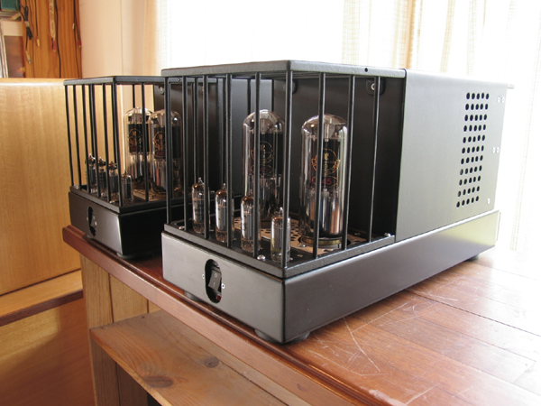
Photo 8.
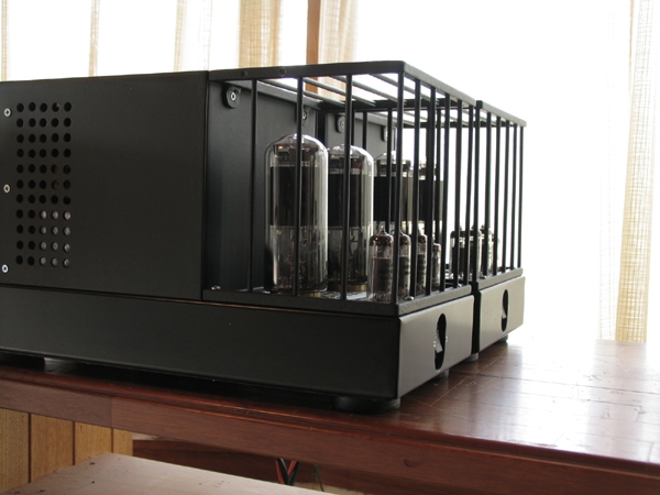
Photo 9.
Back to
poweramps.
Back to index
page.