Push
Pull Output stage configurations. April 2014.
This page is about unusual PP amps with series output tubes in
triode class A, and for use of
UL PP OPTs to obtain local Cathode Feedback for much greater
linearity in the output stage.
Fig 1. Waveforms of signal currents and 2H conventional PP Class
A1 triode amp with OPT with B+ at CT.
Fig 2. Waveforms of signal currents and 2H in series connected
class A1 triode amp with capacitor coupled OPT.
Fig 3. Complete series triode amplifier with bootstrapped
concertina phase inverter/driver.
Fig 4. Complete series triode amplifier with IST used for phase
inverter / driver.
Fig 5. Basic diagram of UL taps used for CFB.
Table 1. UL% used for CFB vs Va, Vk, VRL and Po for Hammond PP OPT
1650P for 6k6 : 4r0.
Fig 6. Complete unconventional UL amplifier which uses 40% screen
taps to provide local CFB from OPT.
Fig 7. KT88 Ra curves for 40% UL taps.
Relevant notes and explanations about all.
There are more ways than one to build tube amplifiers. DIY hi-fi
tube enthusiasts or manufacturers want
good sound while considering........
1. Safety of operation,
2. Low distortion and noise > 0.2% at 1dB below clipping with
rated load.
3. Low output resistance Rout so Damping Factor = Speaker Load /
Amp Rout is greater than 8.
4. Wide bandwidth from 20Hz to 20kHz at least, at full clipping
levels.
5. Adequate output power for the intended speakers.
6. Good load matching to best suit the speaker impedances.
7. Long tube life with Idle Pda of tubes > 0.7 x maximum Pda
rating, adequate air cooling without fans.
8. Use minimum number of parts without compromising technical
operation, and have not too many parts.
9. Ensure the PP amp has adequate initial class A1 power to cover
90% of listener needs, before the amp
begins to work in class AB1.
10. All tubes in amp must work without any grid current with rated
load up to clipping and no input or driver
tube produce more than 0.5% THD at 1.5 x the signal voltage needed
for output tube grids at 1dB below clipping.
11. Build the amp for ease of serviceing and biasing so special
tools other than a screw driver, and no need to
move amp or remove any metal covers or need to read voltmeters.
12. Ensure the amp weighs less than 25Kg. This means use of
monoblocs < 25Kg, and perhaps having remote
PSU < 25Kg.
Many studying tube amps should be aware of the most common PP amps
with at least 2 input / driver triodes
or pentodes to drive 2 output tubes with the anodes connected to
each end of a primary OPT winding with a CT
taken to the B+ supply. Classic examples are the 1947 Williamson,
1953 Mullard 520, Quad-II, Leak2020.
Manley Labs, ARC and other makers followed these old brands,
including my Integrated 5050
which are all
examples of a "conventional" or "normal" PP amp.
To keep explanation simple, pure class A1 is considered first in a
conventional normal PP amp with OPT
with CT on primary.
With a class A1 amp, each of at least TWO output tubes have the
same signal Va-k and Ia waveforms but
all Vac and Iac have opposite phase. But each of 2 PP tubes will
have the same phase of even numbered H
distortion products, with opposite phase of odd number H products.
For PP class A1, each tube works
similarly to a single ended tube.
Where 2H distortion currents have the same phase in each PP tube
and have equal amplitude, there can
be no 2H current flow across the whole OPT primary winding so
these 2H currents in each triode do not
generate 2H distortion voltage in the load. But no two tubes are
perfectly matched, and there is always some
net amount of 2H but at 1dB below clipping net 2H may be only
0.05% while the 3H may be 1.0%. The use
of PP class A1 triodes can give extraordinarily low levels of THD,
and often 6 times lower than if the two triodes
were used in parallel.
Fig 1. Conventional PP output tube wave forms.
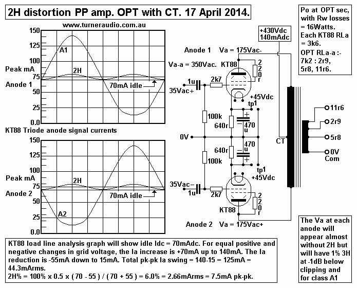
Fig 1 shows a typical class A1 PP output stage with PP OPT with B+
fed to a primary winding CT.
The pure class A operation results in a slight increase of B+
current to each tube and in this case
the idle current level of 70mA is seen, and because of the 2H
production character of the triode
it operates as a rectifier and at the high signal level shown each
tube would require 75mAdc,
and in fact the B+ current will increase from 140mA to about
150mA. This slight rise in PSU anode
current is very low compared to what happens in class AB1 with a
low value RLa-a load and at
clipping the B+ Iadc may double or triple depending on the idle
currents.
------------------------------------------------------------------------------------------------------------------------------------------
Series Push Pull tubes, aka Totem Pole Connection.
Fig 2. Non conventional series PP output tube wave forms.
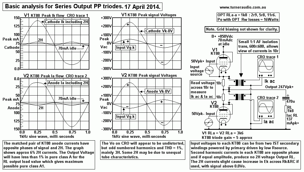
Fig 2 shows that in theory, there isn't anything anything
preventing output tubes being connected in series in
what is called a "totem pole" output tube configuration.
To avoid confusion, and perhaps make it clear why the output with
series tubes is so good, Fig 2 gives
the basic operation of series output triodes without showing the
complexity of a whole amp schematic
including biasing details of the KT88.
To obtain the above information an output stage was set up with
KT88 in triode, each with cathode R+C
biasing networks. This auto biasing for class A was found to give
good Idc control with equal Ea for each
KT88, and of course there MUST always be equal Idc in each KT88
because the pair are in series.
For triode operation the Ia mentioned always includes Ig2, because
g2 is tied to anode via 220r, not shown
above.
A suitable IST with 2 : 1 + 1 ratio was used to drive the pair of
KT88. This IST had 2 isolated secondaries
so one was used for each KT88, but with the two windings producing
opposite phases. The use of the IST
gave very low DC resistance for biasing the grid at voltage at
bottom of Rk+Ck.
The source to drive the IST was from a voltage amp capable of
200Vrms 1Hz to 1MHz at Rout = 1k2.
To view the current wave forms in each KT88, two 10r were placed
as shown and a pair of spare AF
transformers normally used for driving a pair of PNP output
transistors - as they did in 1955, and in a similar
circuit arrangement as I have here.
The transformers allow us to view the current waves on a CRO of
each tube without the presence of the
output Vac appearing at the transformer secondaries. I used a dual
trace Hitachi CRO from about 1983.
The current waves for each tube show us immediately what is going
on with 2H in each tube and why there
is virtually no 2H in the Output Vo. The test circuit could be
driven well into class AB2 and give much more
AB2 Po than the 16 W one can get with pure Class A1.
The Ek across each of the two R+C cathode bias networks begins to
increase with any increase in Vo above
zero signal level. This indicates that Idc is increasing in both
tubes due to slight rectifying behaviour of each tube
due to its 2H generation non linearity. When the input signal
level is pushed above class A the current waves
become most distorted, with perhaps 20% THD with multiple H
present. The 3H at output will then increase
but Vo will have MUCH less distortion voltage present than the %
THD in the current waves. This is true for
all class AB operation.
In Fig 1, the KT88 triodes need a +430Vdc B+ supply with 140mAdc
total Idc at idle.
In Fig 2 for the series connection, the B+ for each tube is in
series hence the B+ rail of +850Vdc with 70mAdc
in each KT88. The HT winding on a normal amp with center tapped
OPT may have a 325Vac winding which
has a diode bridge rectifier to generate about +430Vdc at 140mA
for the 2 KT88 triodes. But for the series
connected tubes the SAME 325Vac HT winding is used with only 2
diodes in a voltage doubler with two
470uF / 450V in series to generate about +860Vdc at 70mAdc, before
being filtered by CLC filter with two
more 470uF caps. The PSU supplies the same anode DC power for the
two configurations.
There is only one Output Voltage, and it is the same for both
tubes. But the signal currents in each KT88 have
opposite phase, and while one triode is increasing its current
flow the other is reducing its current flow.
When the V1 top KT88 is increasing its Ia, the V2 is reducing its
Ia, and the net change in current is applied
to the output load.
One may be forgiven for thinking the top tube works like a cathode
follower. There is no NFB follower action
in Fig 2, and none in the following Fig 3 complete amp schematic.
There could possibly be local series voltage
NFB in the Fig 3 output stage as invented by Technics for use in
OTL amps, but little need for it with output
triodes with a high RLa relative to the low triode Ra. The
Technics circuit is excellent for mosfets and BJTs,
but with tubes the drive voltage supplied to Technics must exceed
the Output Vo, which creates complexity
than is worth the trouble.
Fig 3. Complete amp with series PP output triodes.
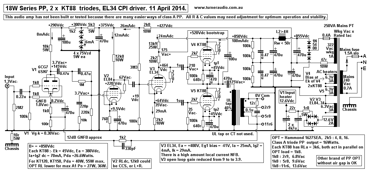 Fig 3 is a complete amplifier with
series output class A1 triodes with cathode biasing.
Fig 3 is a complete amplifier with
series output class A1 triodes with cathode biasing.
B+ = +850Vdc, and Iadc = 70mAdc. Both tubes work with the same
conditions as they would in Fig 1
or similar "conventional" PP class A amp with an OPT with CT.
The power generated by the pair of series tubes is taken from
between 0V and the anode-to-cathode junction
of the two seriesed output tubes. The anode-to-cathode junction is
at a +425Vdc potential while one end of
the OPT primary is directly connected to 0V so there must be a
coupling cap to block Idc flow through OPT
primary which has low winding resistance. I have chosen 470uF.
This capacitor should be bypassed with a
1uF polypropylene rated for +630V.
The V4+V5 triodes are driven by V3 EL34 which acts as a
"Bootstrapped Concertina Phase Inverter Driver."
It is so called because its like all concertina phase inverters
with one triode with equal anode and cathode
resistance loadings, in this case, both 2k2, 10W, rated to take
the 24mAdc in EL34 triode.
Now the top of anode 2k2 is connected to Vo via a "bootstrap" link
formed by 100uF. To get DC flow to V3
and its pair of 2k2, there is a 13k9 resistance to +850V rail. The
output stage Vo is applied to the 13k9 and
the 2k2 and there is a negligible amount of wasted AC power across
the 13k9 resistance.
35Vrms must be generated to drive each KT88 between each g1 and k.
V3 anode resistor of 2k2 has the same current flow as in cathode
2k2, so the SAME 35Vrms exists across
each 2k2, but they have opposite phase. The bootstrapped anode 2k2
means the V3 anode supplies an input
grid voltage at V4 which is 35Vrms greater than the Output voltage
of V4+V5.
There is 35Vrms generated by V3 at its cathode 2k2 from g1 to 0V,
this drives V5 KT88 grid g1.
V3 has to produce a Va-k = 210V + 35V = 245Vac, a large amount of
signal voltage for any driver stage
and to do that with low THD. EL34 in triode has been chosen.
Possibly an EL84 will do, or ECC99, but I
would NOT use a paralleled 6SN7, 6CG7 etc. The EL34 is a man for a
man's job, OK.
The V3 Vg-k = Va-k / open loop gain = 245 / 9 = 27Vac approx. With
35Vac at cathode, the V3 Vg-0V
input = 27 + 35 = 62Vac approx. This voltage produces the 245Vac
total output so gain with the local
current FB = 245 / 62 = 3.95. With low gain due to local current
FB, the V3 will be linear enough.
The signal current in 2k2 = 35 / 2.2 = 15.9mA rms, or 22.4mA peak.
Hence the need for the idle
current in EL34 to be at least 24mA, and it could in fact be
slightly more.
The bootstrapped anode 2k2 means that the anode Vac = 210Vac, and
that the anode load is made
virtually higher than it really is :- 210V / 15.9mA = 13.2k. The
cathode load = 2k2, so total load on V3
= 15k4, which is over 10 x Ra for EL34, so its open loop THD would
be less than 1.5% at voltages
shown, and the effect of the local current FB with 2k2 Rk means
THD of the stage will be about 0.5%
maximum. V3 bandwidth will be excellent, exceeding 150kHz.
Similar driver schematics have been used for OTL amps using
multiple series pairs of 6AS7 or 6C33c.
But readers should realize I have many reasons why I don't like
OTL amps, unless of course you
replace the series output tubes with power mosfets. THEN the same
EL34 driver can be better used
and it will work fabulously well with low operating signal
voltages and negligible THD.
Are there any advantages for using series output tubes?
The traditional PP amp with CT OPT is easier to build and will
give excellent operation with class A1
triodes, even class AB2. The series triodes requires biased heater
supply to the top triode, and a higher
B+ which some will complain that it is too dangerous. But +450Vdc
can kill just as well as +860Vdc.
The series tubes need special understanding, plus a few more
parts, so mainstream makers have mostly
avoided the design.
A notable exception was Philips who used a pair of EL86 in series
class AB1 pentode, with 400Vdc
supply to drive a capacitor coupled 800 ohm load for 10W.
Special speakers were made with 800r impedance using extremely
fine wire in the voice coil.
Unfortunately, although Philips was extremely determined to get
rid of the OPT, they still needed
an OPT to get screen drive to top EL86. The 800r speakers could
not be used with any other amp,
which everyone is tempted to try to do. Th voice coils were very
fragile, and busted easily.
Philips abandoned the series tube idea at about the time in 1962
when the awful solid state devices
began to become reliable enough to make 10W.
Possibly you may want to make use of the series connection where a
suitable OPT is available.
For series KT88 in triode and for Fig 2, each KT88 must see the
same RLa of about 3k3, and the
two tubes work in parallel on the output load which must be about
1k7.
Now you could use a Hammond 1627SEA with an air gapped core to
suit a normal paralleled pair
of KT88 in SE triode, and with 140mAdc flow through the primary.
The 1627SEA has nominal OPT ZR = 2k5 : 4, 8 & 16. If the
wanted load for maximum pure
class A = 1k7, then loads at secondaries must be 2r8, 5r6, 11r2.
These loads are the minimum Z
for many speakers rated for nominal Z = 4r, 8r, 16r. The design
should be based on the speaker
minimum Z and then the amp always works in class A, even with the
lower than nominal ZL.
The 1627SEA can be used if tubes are in series, and output taken
from join of V5 anode and V4
cathode, with Idc blocking cap of 470uF. We do not want Idc flow
in the primary.
In a normal SE OPT with Idc flow, the total maximum Bdc + Bac at
clipping may be 1.3Tesla.
If the total Bac + Bdc go higher the iron caused HD goes too high.
The Hammond 1627SEA is rated for 30W into 2k5, so rated maximum
Vac across primary can be
273Vrms. Hammond OPTs seem to saturate at rated power at 30Hz, ie,
Max Bac is reached at 30Hz
with Va = 273Vrms. But without any Idc, there is no dc core
magnetization, ie, no Bdc, so Bac could
double without saturation. This means that the core will saturate
at 15Hz with 273Vrms and no Bdc.
But we only want to have Vo = 175Vrms and then Fsat < 10Hz.
The primary Lp of 1627SEA is rated as 20H, ( but without any Idc
it would be marginally higher.)
If the primary load = 1k7, then XLp = 1k7 at < 13.5Hz, ie, the
RL in parallel with Lp = 1k2 at 14Hz.
This means the maximum rated power at 1kHz can be maintained right
down to 20Hz without the Lp
wasting a lot of current flow in tubes, and causing high
distortion from overload.
So we get the 1627SEA to work better at LF than Hammond ever
intended.
Hammond do not have any other suitable PP OPTs with CT and which
are rated for about 30W
and with primary RLa-a loads less than 2k0.
One probably very suitable OPT would be the Lundahl OPT with many
available winding strappings,
http://www.lundahl.se/wp-content/uploads/2013/05/1693.pdf
In the past, series output tubes were not ever used because the
expense could never be justified,
although the OPT can be more easily wound with less turns and
thicker wire for a primary, and there
is no problem with balance of Idc in each 1/2 of a normal PP
OPT.
So the conclusion I make is that the series tubes does allow some
OPTs to be used which
otherwise could not be used. In theory, the sound quality should
be excellent with series triodes.
In practice, the Fig 3 amp begs us not to build it.
There are THREE input driver stages, and lots of R+C and C+L
couplings which threaten LF stability
when NFB is used because of increased open loop phase shift at LF.
I suspect 12dB GNFB would be about as much NFB as possible, but
that is enough for any triode
class A amp.
What could be done to make the series triode amp a little easier
to build, with maybe better technical
and sonic results?
Fig 4. Complete amp with series output tubes with SE triode driver
and IST.
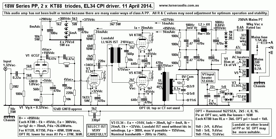
Fig 4 has an IST which may be a Lundahl such as the LL1635 IST.
See
http://www.lundahl.se/wp-content/uploads/2013/05/1635.
The Lundahll specifications are MUCH better than IST from Hammond,
such as their 126B which has
unwanted bifilar windings which will give a high value of unwanted
capacitance between V3 anode and the
output from the KT88. The Lundahl prices are probably horrendous,
but then, do you want to make dreadful
junk or make something better than everyone else? Save your
pennies for the Lundahl.
Most ppl would use an IST with primary between B+ and anode with
an Idc flow in the primary.
But the Lundahl specs say that with Iadc up to 35mA, Vo max =
90Vpk, or 63Vrms per winding.
Better operation is obtained with no Idc, and maximum Vac per
winding becomes 155Vrms, because there
is no dc magnetization of the core. Each of the two windings may
both be used to bias the KT88 grids with
a very low resistance of the winding Rw, eliminating the need for
R&C coupling, excepting what is needed
from EL34 anode to IST primary, which drives V5, with one end of
winding grounded.
The secondary has one end to Vout, and biases V4. Each of the IST
windings will have oppositely
phased signals with equal amplitude. The whole IST secondary is
referenced to Vout, so V4 gets exactly
the same V drive as V5. Hence there is no need for a concertina
phase inverter stage and no need to
produce a high drive voltage, so one whole amp stage can be left
out compared to Fig 2.
KT88 triodes in class A1 as I have them in Fig 3 will each have Ra
= 1k1. The two triodes are in parallel so
Rout at Vo without GNFB = 550r, and with RL = 1k8, the Damping
Factor without GNFB is a healthy 3.2.
Winding resistance may lessen this slightly. The GNFB will
increase the DF to at least 12 because the 550r
is reduced to at least 140r.
While much adulation is now given to KT120, KT150, it is still
better to use 4 x KT88 / 6550 than
2 x KT120 or KT150. The simple reason is that 2 parallel KT88 on
each side of a PP circuit have twice
the gm, half the Ra, and better manage a lower load than 1 x KT150
on each side of PP circuit. The KT88
can run with less Iadc and total Pda so they will last longer. The
rated maximum Pda for KT150 is 70W,
but only a fool would idle one at that level, and maximum idle Pda
is probably better at 50W max, so two
can have Pda = 100W and maximum triode efficiency = about 33% so
hence max class A triode Po = 33W.
The KT150 in pure beam tetrode mode is far from linear, like most
other power tetrodes and power
pentodes. But in a PP amp with CFB, then they will be excellent
just like the others because of the way
the local NFB is used.
Use of KT150 will give the most interesting results because they
look so spectacular, so much is
expected of them. But let us consider if they were used instead of
just 2 x KT88 with idle Ea = +380V.
KT150 could be safely biased for Pda = 45W so Iadc = 45W / 380V =
118mAdc.
For max Class A1, RLa = ( 380V / 0.118A ) - 2,000 = 1,220 ohms.
But RLa should be at least twice
Ra for all class A triodes, and Ra is about 1k0. So, Ea would need
to be higher, so let us choose
Ea = +450Vdc. This means changes to PSU to use more rail caps
because the B+ with cathode bias
for series tubes will be maybe +1,020Vdc. With Ea at +450Vdc, and
Pda = 45W, then Iadc = 100mAdc
so RLa = ( 450V / 0.1A ) - 2,000 =2,500r. The Series pair needs RL
= 1.25k.
Therefore a Hammond 1640P could be used, nominal ZR = 1.25k : 4r0,
8r0, 16r0, and quite OK.
Maximum Po = 25W for pair. The outcome is remarkably similar to
using ONE SE 845 with Ea
= 1,050Vdc and OPT 12k0 : 4r0, 8r0, 16r0. Suitable OPT for 845 are
not easy to find.
---------------------------------------------------------------------------------------------------------------------
Use of generic Hammond 1650P or 1650PA.
Hammond 1650P specifications allow 60W class AB1 with normal 40%
UL with 2 x KT88 or 6550.
Initial class A1 = 7.6W for RLa-a = 6k6, with secs able to be
linked for 4r0, 8r0 and 16r0.
Each KT88 will have idle Ea = +505Vdc and Ia = 48mAdc, with Ig2 =
6mAdc, so that Pda+Pdg2 = 27.3W.
Idle Pda alone = 24.3W. For 2 x KT88, safe total idle Pda = 2 x
24.3W = 48.6W and max anode class A Po
= 23W, and OPT winding losses of 5% reduce this to 22W approx. But
the anode load for anode Po 23W
with Ea and Ia as specified must be about 20k0, so that OPT would
need to have ZR = 20k : 4r0 = 5,000 : 1,
abd TR = 70:1, and the Hammond 1650P has no such OPT ratio. Its
highest TR is for 6k6 : 4r0, ie, 1,650 : 1
with TR = 40.6 : 1.
For the max possible class A for 6k6 : 4r0 OPT, and with 2 x KT88
at Pda = 26W each, idle Ea = 310Vdc,
Ia = 84mAdc, and maybe you get 22.5W class A1 at sec output with
5% winding losses. Use of lower loads
at OPT sec will give lower RLa-a and higher max Po which becomes
class AB. If sec load was 1r1 then RLa-a
becomes 1k8, and winding losses = 21% so total RLa-a + Rw = 2k2,
and max anode Po = 37W AB1, but
at sec the Po = 29W, not much more than the maximum class A Po
available, and THD is too high.
However, class A Po for 4r0 will tolerate load dips to 3r0 very
well.
But no matter what is done, the use of only 2 x KT88 with 1650P
cannot give the the best class A.
Use of 4 x EL34, 6L6GC, KT66 would be better. There are large
worldwide stocks of these tubes which are
still being made and I suggest 2 x EL34 can do the same job at 1 x
KT88 and maybe for same price. The idle
Pda for each EL34 or 6L6GC can be a mild 21W, so total idle Pda
for 4 x EL34 = 84W.
Possible anode class A1 Po = 46% x 84W = 38W, and if winding loss
= 4%, expect 36W at sec output.
Where class A PP RLa-a load = 6k6, the class A RLa for each side
of PP output circuit = 3k3.
For all beam tetrodes or pentodes RLa for SE class A may be
calculated RLa = 0.9 x Eadc / Iadc.
And Idle Pda = Ea x Iadc, so Iadc = Pda / Ea. Thus RLa = 0.9 x Ea
squared / Pda.
Thus Ea = sq.rt [ Pda x RLa / 0.9 ].
For 2 x EL34 on each side of PP circuit, Idle Pda = 42W, and RLa =
3k3, so for this case,
Ea = sq.rt [ 42 x 3,300 / 0.9 ] = 392Vdc.
Iadc = Pda / Ea = 42W / 392V = 107mAdc.
For 2 x EL34, Class A Po max = 0.5 x Iadc squared x RLa = 0.5 x
0.107A x 0.107A x 3,300r = 18.8W.
Thus 4 x EL34 make 37.7W class A1 at anodes, and with 5% winding
loss expect 35W+ at sec output.
If one EL34 is considered with idle Ea = 392V and Ia = 54mA, its
class A RLa = 6k6, and anode Po = 9.4W.
This is a beautiful outcome. The load could be reduced to find the
maximum possible class AB Po which may
be 55W, but all without Va-a ever exceeding 512Vac. Hammond 1650P
is OK for 60W to 6k6 where Va-a =
630Vac, and where it is expected that Fsat = 30Hz, so with Va-a
max = 512Vac, expect Fsat = 25Hz, not too
bad for a cheap and affordable OPT.
For the really adventurous amplifier builder, I now submit a
design which allows use of Hammond 1650P with
2 x KT88 with Pda each 27W but with completely radical way of
using 40% UL screen taps to connect to tube
cathodes to get CFB operation = 28.6%, but without a special OPT
with has a dedicated tertiary winding for CFB.
Fig 5. Basic use of UL taps for CFB.
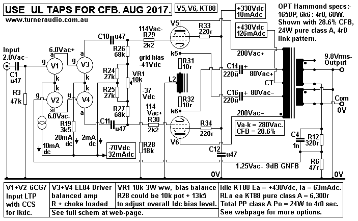
Fig 5 is a basic diagram showing V1+V2 6CG7 and V3+V4 EL84 drawn
as 4 circles which provide 2 inputs,
one for signal from CD player, one for GNFB. There are two
opposite phases of 114Vrms maximum produced
by balanced amp with 2 x EL84.
The output stage has Hammond 1650P set up with +430Vdc at primary
CT, and fed with 126mAdc. KT88
have idle Pda = 27W with Ia = 63mAdc, and screens are fed from
+330Vdc rail.
Each 40% UL tap is connected to tube cathode bias 200uF caps where
UL tap is on opposite side of CT to
anode connection. This is aka as cross coupled cathodes.
The 220uF only allow Iac flow and Idc flow from each cathode is
through 10r0 and 1/2 of choke L2 and to
0V at choke CT.
L2 choke = GOSS E+I with minimum µ = 5,000, T25mm x S20mm and
window L37mm x H12.5mm.
This allows 3,000 turns of 0.25mm Cu dia wire with a CT. The
inductance > 200H. Reactance at 10Hz
= 12k6. Loading effect on OPT at 10Hz and 160Vk-k is 2W and
negligible at higher F. At max Bac 1.5T,
Fsat = 16Hz, and is well below Fsat for OPT. The 0.25mm Cu dia
wire can have 100mAdc at 2A/sq.mm, and
will survive 500mAdc from faulty KT88 until an active protection
circuit turns off the amp or a 200mA fuse
blows where it is in sereies with each cathode and choke winding.
C14+C15 carries all Iac flow, and I show 220uF x 450V rated but
should have plastic bypass of 0.47uF 630V.
The whole OPT winding is at +430Vdc, and cathodes are at about
+2Vdc.
The OPT primary has 200Vac at each end of primary and 80Vac at
each 40% UL tap. So for V5, with
+200Vac at anode from top of OPT primary as drawn, its cathode is
connected to -80Vac at UL tap below the
primary CT. Thus Va-k = 280Vac. Assume V5 and V6 are working in
pure class A. Thus Ia change
= +/-63mApk = 0.044Arms, and class A RLa for each tube = 280V /
0.044A = 6,363r. Anode Po for each
tube = 12.3W, and total for 2 = 24.6W and with 5% winding loss for
OPT, Po at sec will be 23.4W.
But what RL will be at sec?
Consider conventional PP operation for 1650P with Va-k = +/-
280Vac for each 1/2 primary, so Va-a = 560Vac.
Assume each KT88 works in pure class A with its RLa = 6,363r so
that RLa-a will have to be 12,726r and if
1650P has sec linked for 4r0, ZR = 6k6 / 4r0 = 1,650 :1 so the
load used must be RLa-a / ZR
= 12,726r / 1,650 = 7r7. OPT has TR = 40.6 for 4r0 linking, so Vo
at sec = 560V / 40.6 = 13.79Vac for 7r7,
so Po = 24.7W, and 5% winding loss reduces this to 23.5W.
Each KT88 acts like an SE tube in amp with RLa 6,363r and OPT
primary = 1/2 turns of PP OPT so in this
case with TR = 20.3 : 1 and ZR = 412 : 1 so sec RL = 6,363r / 412
= 15r4.
With 2 x KT88, and each working into 1/2 the turns of OPT in
series, then 2 equal sec windings with 15r4 each
act like one sec comprising 2 paralleled windings and load = 7r7.
But in Fig 5 above, each KT88 works with increased number of
primary turns, The portion of primary turns
between each UL tap is used by both tubes. Thus the turn ratio for
eack KT88 of pri to sec is increased.
The effective TR used = conventional TR x ( 1 + UL fraction ).
Conventional TR for class A for each 1/2 primary to sec = 0.5 x
40.6 for 1650P = 20.3.
40% UL gives UL fraction = 0.40. Effective TR = 20.3 x ( 1 + 0.4 )
= 28.42.
Thus ZR = 28.42 squared = 807 : 1. Thus each KT88 in class A works
like SE amp with RLa = 6,363r
and sec load = 6,363r / 807 = 7.88r, and with 2 x KT88 there can
be one sec winding loaded with 3.94r,
and this is what is present in Fig 5.
The cross coupled cathode connection could be done where UL % =
100%, and then each KT88 would
work with the whole length of primary as is the case with a
Circlotron amp and Va = Vk = 140Vac.
Table 1 is for 2 x KT88, Ea = 505Vdc, Ia = 48mAdc.
Table 1. UL% used for CFB vs Va, Vk, VRL and Po for Hammond PP OPT
1650P for 6k6 : 4r0.
PP
UL %
|
UL
fraction |
Nominal
RLa-a
|
Sec
RL
|
Class A
RLa
|
Class B
RLa
|
Va-k
|
Va
|
Vk
|
Va-a
|
Vk-k
|
CFB
% |
Vo
RL
|
Max total
A1+AB1
Po W
|
Class
A1
Po W
|
0%
|
0.0
|
6,600r
|
4r0
|
3,300r
|
1.650r
|
315
|
315+
|
0.0
|
630
|
0.0
|
0.0
|
15.5
|
60.0
|
7.6
|
20%
|
0.2
|
9,504r
|
4r0
|
4,752r
|
2,376r
|
315
|
263+
|
52-
|
526
|
104
|
16.5
|
12.9
|
41.8
|
10.9
|
20%
|
0.2
|
6,600r
|
2.8r
|
3,300r
|
1,650
|
315
|
263+
|
52- |
526
|
104
|
16.5
|
12.9
|
60.0
|
7.6
|
30%
|
0.3
|
11,154r
|
4r0
|
5,577r
|
2,788r
|
315
|
242+
|
73-
|
484
|
146
|
23.0 |
11.9
|
35.0
|
12.8
|
30%
|
0.3
|
6,600r
|
2r4
|
3.300r
|
1,650r
|
315
|
242+
|
73-
|
484
|
146 |
23.0
|
11.9
|
60.0
|
7.6
|
40%
|
0.4
|
12,936r
|
4r0
|
6,468r
|
3,234r
|
315
|
225+
|
90-
|
450
|
180
|
28.6
|
11.0
|
30.6
|
14.9
|
40%
|
0.4
|
6,600r
|
2r0
|
3,300r
|
1,650r
|
315
|
225+
|
90-
|
450
|
180
|
28.6
|
11.0
|
60.0
|
7.6
|
50%
|
0.5
|
14,850r
|
4r0
|
7,425r
|
3,712r
|
315
|
210+
|
105-
|
420
|
210
|
33.3
|
10.3
|
26.5
|
17.1
|
50%
|
0.5
|
6,600r
|
1r8
|
3,300r
|
1,650r
|
315
|
210+
|
105-
|
420
|
210
|
33.3
|
10.3
|
60.0
|
7.6
|
60%
|
0.6
|
16,896r
|
4r0
|
8,448r
|
4,224r
|
315
|
197+
|
118-
|
394
|
236
|
37.5
|
9.7
|
23.5
|
19.4
|
60%
|
0.6
|
6,600r
|
1r6
|
3,300r
|
1,650r
|
315
|
197+
|
118-
|
394
|
236
|
37.5
|
9.7
|
60.0
|
7.6
|
100%
|
1.0
|
26,400r
|
4r0
|
13,200r
|
6,600r
|
314
|
157+
|
157-
|
314
|
314
|
50.0
|
7.7
|
14.8
|
14.8
|
100%
|
1.0
|
6,600r
|
1r0
|
3,300r
|
1,650r
|
314
|
157+
|
157-
|
314
|
314
|
50.0
|
7.7
|
60.0
|
7.6
|
Table 1 shows the use of UL taps for CFB with UL % = 0.0%, 20%,
30%, 40%, 50%, 60% and 100%.
With UL% = 0.0%, KT88 are in pure beam tetrode mode and Va-a =
630Vac, for 60W into 6k6 : 4r0.
But for CFB use with UL taps, and as UL% is raised above 0.0%, the
amount of OPT primary winding used
by each KT88 increases from a minimum of 1/2 the whole primary to
all of the primary. This effectively
increases the OPT ZR from 1,650 : 1 with 6k6 : 4r0 with 0.0% UL%,
to maximum 26,400 : 1 even though
the real turn ratio remains the same for all above Vac conditions
where 6k6 : 4r0 has TR = 40.62 : 1.
With the maximum 100 UL% used, each KT88 applies 314Vac in
opposite voltage phases but same Ia
phases to all pri turns, and in fact the 2 x KT88 are effectively
working in parallel on one pri winding, where
effective TR is double that for the 2 x KT88 act in series for
0.0% UL, ie, normal PP OPT use.
Thus for 100% UL taps the 2 x KT88 work like any 2 tubes used in a
Circlotron or in a McIntosh output.
However the McIntosh OPT uses two primary windings each with CT,
with one for anodes with B+ potential,
and one for cathodes at 0V potential and wound bifilar to make
what is effectively one winding with the same
Vac phase for both windings. Also, the McIntosh has each screen
connected to an end of pri winding where
there is the same Vac phase as cathode, but also same B+ as at
anode, so the two KT88 are effectively
working in pure beam tetrode mode but with 50% CFB, and this makes
the gain higher than for where screens
are connected to a fixed Eg2.
To make a "poor man's McIntosh", TWO identical 30W OPTs could be
used with one used in anode circuit
with CT to +505V and other in cathode circuit with CT of 0V. The
ends of windings would all have 157Vac,
and where the 2 windings have same phase of 157Vac, caps of 220uF
// 2uF are used to get the pair of
primaries to work as ONE winding as in McIntosh.
The problem with McIntosh arrangement is that with 157Vac at
cathode, the grid Vac must be higher and if
Va-k / Vg1-k gain = 10, which could be the case with a low B RLa
load for class AB1, then Vg1 - Vk must
be 314V / 10 = 31.4Vac so Vg1-0V supplied by driver stage from
each driver tube anode = 188.4Vrms.
This is much more difficult to do than if UL% of 40% is used, and
where there is the same loading and same
gain = 10 and Va-k 315Vac, and where Vk = 90Vac, so Vg1-0Vac =
90Vac + 31.4Vac = 121.4Vac.
In Fig 5 above, I have 40% UL taps with both KT88 having Va-k =
280Vac, one with Va = 200Vac+, Vk = 80V-,
and other with Va = 200Vac- and Vk = 80V+.
The peak Va swing = 396V.
The Ea = +430Vdc and B+ would be slightly more to allow for Vdc
across winding resistance.
Idle Ia = 63mAdc, and load line analysis shows that for pure class
A1, Va will swing down to a point on diode
Ra curve where max class A Ia = 126mApk, and minimum Ea = 32V, so
Vapk swing = 430V - 32V = 398V,
and class A RL = Vapk max / Iapk change = 398V / 0.063A = 6,317r.
Thus the max class A anode Po for
each KT88 = 12.5W, so 25W for both KT88. Not including winding
losses and with Va-a = 2 x 200Vac,
Vo at sec = Va-a / TR = 400V / 40.6 = 9.84Vac, and if anode Po =
25W, sec load + total Rw at sec = 3.88r.
IRL = 9.84 / 3.88r = 2,54Aac. The real load at OPT sec = 3.88r -
5% Rw = 3.69r, so VRL = 9.3Vac, with
real sec Po = 23.5W.
Fig 5 does not include winding resistance of Hammond 1650P. But
all calculations are aproximately correct, and
a 4r0 load may give slightly less class class A than for 3r7, but
operation predictions don't need to be more accurate
than I have explained here.
If the RL at sec was half the 3r7, say 1r8, then the class A RLa
for each KT88 is 0.5 x 6,317r = 3,158r, and each
tube will have part of wave cycle with zero Ia, and other tube
woking with class B RLa = 1,579r and max anode
Po = 44W AB1, winding loss = 13%, and Sec Po = 38W. Initial class
A = 12.5W.
Fig 6. 40W PP amp with Hammond 1650PA 40% UL taps for 28.6% CFB
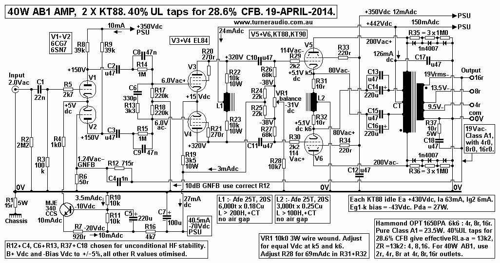
Fig 6 shows a complete amp with Hammond 1650PA output transformer
with 40% UL taps and tapped
secondary winding for 4r0, 8r0, 16r. The 1650PA has the same Po
rating for 60W to primary load 6k6
as the 1650P which has sec windings which allow for links to get
lower winding losses than 1650PA.
Fig 6 could be used for any existing amp wherever the OPT has UL
taps if there is enough chassis space
available because most manufacturers used a small chassis with
barely enough space for the fewest small
items they were prepared to include.
The driver stage does have to generate a high maximum 114Vac to
each output grid. but a pair of EL84 will
do well, and many existing amps will only have one mini 9 pin
socket for a 6BH7 which can be used as LTP
to make high Vac. McIntosh used 12BH7, and I have used it, and
each triode has Ra = 4k4, µ = 17.
6BL7 is a good octal twin triode with each triode having Ra = 4k0
and µ = 15.4 at Ea 300V and 12mAdc,
and with high Pda rating. ECC99 could also be used and and each
triode has Ra = 2k5, µ = 21 so that one
of its triodes equals EL84 in triode. But ECC99 triodes have Pda
limit of 5W, so idling at 3.6W with
300V x 12mA is asking a lot.
Instead of having CT choke for high Z dc load to anodes, R22 and
R23 10k may bootstrapped by
connecting their B+ ends to UL taps on OPT at -80Vac of +80Vac.
The Vac across each R22 and R23
= 114Vac - 80Vac = 34Vac, so Iac = 3.4mAac, and each 10k
effectively becomes a load
= 114Vac / 3.4mAac = 33.5k.
To increase the RLa load further, R26 and R27 68k may have 15k
added to each to connection to VR1
pot for -38Vdc bias. The join of 68k+15k is then bypassed to
nearest cathode with 2u2 so that each 68k
effectively becomes load = 228k. If 6BL7 is used, total RLa for
each anode = 33k // 228k = 28.8k.
Gain = 13.5, so 6BL7 would need 8.3Vac to each grid. Gain of V1+V2
6CG7 = 15.8, so their Vg-g
= 1.05Vac, and to get 10dB GNFB the Vin will need to be 3.0Vac,
with NFB at V2 g1 = 1.95Vac.
To make the amp input more sensitive I suggest V1+V2 = 6DJ8 which
would give gain = 26 with RLa
shown so that Vg-g = 0.64Vac, and NFB network may remain
unchanged.
The other choice of 60W Hammond UL OPT is the 1650N which is 4k3 :
4r0, 8r0, 16r0.
To get 60W AB1 for 4k3 needs 2 x KT88 with idle Ea = 450V and Ia =
60mAdc.
If 40% UL taps are used for CFB, then RLa-a is effectively
increased to 1.4 x 1.4 x 4,300r = 8,428r.
The result should give initial class A = 14W with max AB1 Po = 35W
which is a satisfactory outcome.
KT120 could be used with higher Iadc = 78mAdc, increasing initial
class A to 24W.
But do not expect a huge sound change if you use KT90, KT120 or
KT150 instead of KT88 or 6550.
----------------------------------------------------------------------------------------------------------
If you do the load line analysis for KT88 or 6550 with Ea at
+425Vdc, Ia at 60mAdc, the class A load
for each tube may be plotted.....
Fig 7. The crazy Ra curves for KT88 with 40% UL taps.....
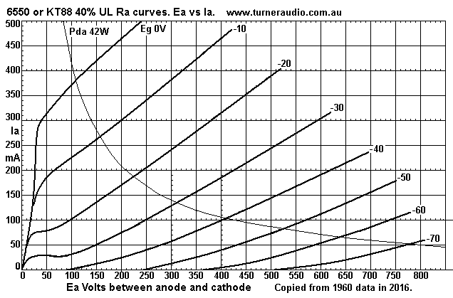
These Ra curves for a single KT88 or 6550 with 40% UL taps may
seem strange because the knee of
Ra curves below Ea 100V all have different shape and show the
diode line between 0.0mA and 300mA
to be a curve and with R value = 133r, little different to pure
beam tetrode curves. But above 300mA
the Ra curve for Eg1 = 0V has Ra = 1k0. Testing tubes to get the
correct shape of Ra curves below
Ea 150V always seems to have been difficult, and I have generally
assumes KT88 / 6550 UL diode
line to be a straight line from 0.0mA x 0.0V to 100mA x 400V, ie,
Rd = 250r. Above 400mA, the Rd
curves over to left to 500mA and this more easily covers all my
design work for UL with KT88 or 6550.
Where 40% UL taps are used for 28.6% CFB and with screens taken to
a fixed +Vdc rail, the Ra curves
for KT88 will look very unlike any UL curves and will be more like
triode curves but at 60mA x 425V the
Ra = 540r so the slope of curves for this mode will be much
steeper and straighter than for KT88 in triode.
Notice that the UL curves have a slope which are intermediate
between fairly flat Ra curves for pure tetrode
and the steeper slopes of triode connection. The pure tetrode Ra
will be about 30k at 60mA x 425V.
The triode Ra will be about 1k1 at same Ea and Ia. The Ra for the
above UL is above 2k4.
Using formulas for class A Po isn't always the best idea unless
you know what you are doing, and to know
more I suggest you visit loadmatch-4A-PP-tetrodes-pentodes.html
and following pages.
The 3 main Hammond PP OPT worthy of consideration for 4r0, 8r0,
16r0 are :-
1650N 4k3 60W 3.6Kg or 8lb, for 2 x KT88, 6550, KT90, KT120
KT10 4 x 6L6GC, KT66, EL34.
1650P 6k6 60W 3.6Kg or 8lb 2 x 6550, KT88, KT90, KT120, 4 x
EL34.
1650R 5k0 100W 5.4Kg or 12lb 2 x KT120, KT150, 4 x 6550, KT88,
6CA7, EL34.
---------------------------------------------------------------------------------------------------------
Making L1 and L2 chokes.
L1 and L2 chokes are a challenge to make, but are much easier than
making an OPT !
L2 should have GOSS E+I or C-cores with Afe T25 x S20 x L37 x H12,
( mm sizes.)
A small E+I mains tranny with 20VA rating may have a core that is
suitable and it may be heated on a small
wood fire until dull red, then allowed to cool slowly. The heat
vaporizes all plastic and varnish and windings
can be cut off. The Es and Is will fall apart easily, ready for
use again, unaffected by heat. 0.25mm Cu dia
NEW winding wire must be used. You may have to make a new bobbin
from glued 1.6mm thick fiberglass
sheeting, or you may find a supplier for moulded plastic
transformer bobbins. A bobbin with centre divider
is preferable, and you should be able to wind on 1,500t of "random
turns" using rotation speed of < 5turns/sec.
The two ends of winding are brought out and wound around heads of
screws in bobbin holder on lathe.
Then a second 1,500t is wound on, and ends secured so that they
cannot easily be caught in something and
broken off within the bobbin. If that happens, the turns must be
removed and re-wound.
The wire is fed on through hands resting on bar between you and
the lather, and wire slowly traversed across
bobbin in both directions while sometimes slowing to add
more turns where height of winding is least.
Spray clear varnish on for each 100t until winding looks well wet.
Do not use too much wire tension or too
little, and the slow traverse rate will avoid wires crossing over
other at more than 10 degrees, thus avoiding
pressure spots on wires. This method of choke winding is without
layered turns and insulation between each
layer and has been done since well before 1900 when by then there
were many uses for coils of fine wire with
many turns of fine wire. Enamel insulation of Grade 2 is now
usually polyester-imide, rated for 200C and far
better than anything used in 1900.
The bobbin should have 3 terminals mounted on cheeks to for wires
to be wound around and soldered.
Before soldering, a small knife blade is used to scrape off enamel
to allow wires to adhere to bare copper.
The wet varnish will set hard over time and prevent wires from
moving with change of magnetic field.
The turns must be counted accurately, and my home made lathe uses
an automotive odometer counter
mechanism. I have a steel lathe shaft dia = 12.5mm, with wheel on
counter = 125mm, and wheel and counter
can read up to 1,000 and both are on swing arm held to shaft with
a spring. The 125mm wheel moves one turn
for 10 turns of wire. The movement on counter is easily seen with
1 turn of lathe shaft, and I filed the 125mm
wheel down until I could count 1,000 turns, and the odometer read
exactly 1,000. The odometer will read turns
being removed, in the same way as it reads kilometers when
reversing in a car. ( Second hand car salesmen know
they must drive a car backwards for 50,000km so that the original
reading of 70,000km is reduced to 20,000km,
so its easier to seel the car at a higher price. )
Don't be tempted to get some electronic turn counter unless it is
as accurate and reliable as my simple mechanism.
It is possible to use a chain drive or gear drive with exact 10 :
ratio, but if the small chain ring is 30mm dia, then
large ring on odometer must be 300mm, and it get in the way of
everything you do and may easily break the shaft
of odometer mech.
My copper clad wheel made from 10mm DDF 126mm dia plus counter
lays against smooth 12.5mm dia lathe
under spring tension and it is easy move the wheel off the shaft
to spin the wheel to an exact 0.0 turns.
Usually there is enough chassis space for such a small sized
choke. PVC insulated wires to and from choke may
be 200mm long to where choke is mounted for least stray magnetic
coupling to a PT or OPT and oriented so
lines of magnetic force are at 90 degrees.
L2 inductance should act as a high L reactance element for
allowing Ikdc from each KT88 to flow to 0V and to
PSU. Common mode Vac at cathodes is prevented, but inductance can
be up to 200H if iron µ = 5,000.
This will give XL = 12,600r at 10Hz, and with Vk-k = 160Vac, Fsat
= 16Hz, to the choke has negligible effect
on signals at cathodes. Cathode input Z < 200r, which is low
enough to reduce any iron caused 3H distortions.
L1 choke uses same size and type of core and bobbin as L2. But
wire = 0.180mm Cu dia, and it should be
possible to easily get 6,000 turns on, and with a CT, and L should
be 4 times L for L2, so XL2 at 10Hz should
be 50k, and with Va-a = 228Vac, Fsat = 12Hz. The phase shift
effects of shunt L at low F and and shunt C at
high F are prevented by series R22 + R23, and if one EL84 anode
shorts to 0V, then maximum Idc flow from B+
= 44mAdc through 10k which generates 19W, well above the 1.4W of
normal operation with 12mAdc.
I show R22 and R23 rated for 10W, and they may fuse open over time
with a short circuit but music will sound
so bad with V3 or V4 at 0V that an owner will get the amp
serviced.
The pair of EL84 set up as I have them will make THD < 0.1% at
Va-a = 200Vac, and less than using just a
single 6SN7 with its two triodes making Va-a = 70Vac. I have used
EL84 in triode in numerous amps as drivers,
in my 300W
monoblocs, 8585 amps.
A good driver stage is essential for any output stage tube. The
sound you hear is the sum of the parts used.
Input and driver tubes can affect the sound as much as the output
tubes.
To minimize the driver amp THD, the input stage must also be
linear, best done with an LTP which produces a
balanced pair of opposite phases with very low THD. The twin
triode for input is ideally 6CG7 / 6SN7,
and with a CCS for cathode current.
Figs 5 + 6 show 28.6% of local NFB in output stage which equates
to about 10dB local NFB with output
stage that effectively has same open loop gain as for normal UL
amp with 28.6% UL taps. Because the input
and driver amp are so linear, their contribution to the probable
0.5% THD of output stage at 24W is negligible.
But the 10dB GNFB reduces ALL THD and IMD of both input, driver
and output stages so that THD should
be less than 0.17% at 24W.
Any amp with a Hammond OPT should be able to be made
unconditionally stable., ie, the amp will not
oscillate with any possible combination of L, C and R at output,
or with no load at all. The the leakage
inductance of these OPT is not as low as I would prefer.
Fig 6 has LF gain shelving networks after V1 and V2 anodes see
C2+C8+R14+R17, and C3+ C9+R15+R18.
As F reduces, response is -3dB at 15Hz due to 47n + 220k. The
response flattens below 3.4Hz pole to
be -14dB below 0dB, and 0.47uF + 1M0 + 220k gives -18dB at 0.28Hz
pole and response falls at -6dB/octave.
The effect of 47n + 1M0 is reduce the V1 and V2 gain by -14dB
between 0.3Hz and 3.0Hz where the amp is
most likely to oscillate due to combined phase shift in input and
driver stage C+R coupling plus R+L coupling
or output tubes to load with OPT which has primary inductance
shunting RLa-a.
The C+R values for LF networks I show will prevent LF oscillations
in most tube amplifiers and should not need
to be changed.
The open loop response reduction below 15Hz without GNFB and with
LF networks will be corrected by GNFB
to give closed loop response -3dB pole at about 5Hz with rapid
rate of attenuation, but without any response
peak or LF oscillation.
The HF gain of V1+V2 is effectively shelved by R6 330pF + R13 3k3.
The Ra-a of V1+V2 in parallel with
their R loading = 20k. The 330pF gives -3dB pole at 24kHz, and
response reduces to -16dB below 0dB
for F above 200kHz. The GNFB tries to correct this to extend the
initial 24kHz pole to about 50kHz but
the amount of applied GNFB above 24kHz is reduced so much the amp
remains stable at HF with R load.
However, overshoot on 5kHs square waves may be exceed +6dB and
pure C loads of 0.22uF may cause HF
oscillations above 50kHz so the C12 1nF is needed across R12 712r
to advance phase of NFB applied to V2.
In addition, Zobel network R37 10r0 + C18 47nF may be
needed.
These values mainly depend on the LCR characteristics of the OPT
and they cannot be fully defined.
The OPT behaves a band pass filter with -6dB / octave attenuation
below say 10Hz, and with -12dB / octave
attenuation above 30kHz with L+R, and R+C, with resonances
of LL and Cshunt. The effects of OPT LCR
properties become most apparent when R source driving the OPT is
lowest.
To damp the effects of HF resonances due to L+C, the Zobel
networks such as C6+R13 and C18+R37 are
needed. But additional Zobel R+C may be needed across OPT 1/2
primaries, say 4k7 5W + 1nF between OPT
anode connection and B+, or from anode connection and UL tap used
for cathode connection, so that the KT88
begin to see a resistance loading at above 32kHz without the
effect of series leakage inductance. At 100kHz,
the reactance of 1nF = 1k6, and with 4k7 in series, their total Z
is mainly resistive and about 5k0. But at 20kHz,
the Z = 16k for C in series with 4k7 so loading effect is
negligible.
Stabilization of amplifiers like this one require deep
understanding of basic LCR behaviour. You don't need to
know the extremely complex maths, but you do need to realize
practical application of basic concepts.
I often used a 3 gang AM radio tuning cap giving 50pF to 1,500pF
plus a 25k pot in series to find R + C
values for C6 +R13 or C4 to get the lowest amount of square wave
ringing with 10kHz square wave and with
0.22uF for load at amp output, and at low levels < 2Vac when
oscillation is most likely. When long ringing
with C load and highest F pole for resistive load is found, pot R
and variable C values are measured, and
replaced with fixed R and C and all re-tested to make sure work is
correct.
You must chose the R+C values by initial calculations, and then
adjust during trial and error process using
oscilloscope. I have received countless emails from DIYers who
have tried to make their own amps but
who found that their amps oscillated at both LF and HF, and it was
not what they expected.
Most DIYers have no idea about how to consider the amp as an
active bandpass filter with loops of NFB.
Most don't understand the principles of Nyquist theory so they
make amps which become fine oscillators,
and that is to be avoided like the plague!
To
Education and DIY directory
Index Page