OUTPUT TRANSFORMER ANALYSIS.
Frequency behaviour, December 2008.......
This page analyses and compares frequency behavior for OPT-1A
which I designed and
another OP1 wound by another maker and which has far more
interleaving which gives
higher capacitance and lower leakage inductance.
The OPT can be the main item in an amp which determines the F
response and bandwidth
for maximum output power where THD remains less than 0.2%, with
NFB applied.
Without any applied negative feedback, the OPT is often the main
item which determines
the open loop amplifier frequency response and phase shift between
input and output signals.
Readers will need to be able to understand the basics about second
order LC filters and
interpreting equivalent models of LCR circuits. Wherever you have
an audio frequency isolation
transformer driven by a source resistance with separate primary
and secondary, you will have a
low pass filter with source R feeding load R through LL and a
capacitance shunting the load R
output to 0V.
Before trying to describe the differences between two styles of
OPT winding, I need to explain
a typical "ultralinear" aka UL PP class AB1 output stage. To keep
things simple, the model uses
my OPT-1A as the OPT and the pair of output tubes are KT88, but
could be 6550, KT90, KT120.
The idea of a model describes the signal function without
consideration of dc idle conditions.
Each KT88 is considered here to consist of a Vac generator with
its Vo = µ x Vg. Its output
resistance is a theoretical zero ohms. 2k5 has been added to mimic
the real Ra of the KT88
which has its screen g2 taken to 50% UL taps on OPT primary
winding between 0V and anode.
The g2 connection need not be shown for the model. Elsewhere I
have explained the effect
of having 50% of the anode Vac applied to g2. KT88 screen g2 gm =
about 0.8mA/V. The Ra
of KT88 is about 30k with g2 fed by a fixed Eg2, but where g2 is
fed by a fraction of anode Va
then g2 provides NFB to the tube where the Vac feeding g2 produces
anode Iac that is opposite
to the action of control grid g1.
With g2 connected to anode for triode operation, all the anode Va
appears at g2 and Ra is then
as low as it can be.
Ra' of KT88 with fraction of Va applied to g2 = Tetrode
Ra parallel with ( 1 / gm g2 x UL Fraction ).
In this case, with 50% UL, fraction = 0.5, Tetrode Ra at idle =
30k, gm g2 = 0.8mA/V.
Ra' KT88 = 30k // ( 1 / 0.5 x 0.8mA/V ) = 30k // 2k5 = 2k3.
If the UL% = 0.0, fraction = 0.0, so operation is pure tetrode so
Ra = 30k.
If UL% = 100%, fraction = 1.0, and operation is triode, Ra' = 30k
// ( 1 / 0.8mA/V ) = 1k2.
For all tubes, amplification factor µ for g1 = gm g1 x Ra.
Input grid g1 gm at idle condition = 5.5mA/V approx, and here I
have UL Ra = 2k3,
so UL µ = 0.0055A/V x 2,300r = 12.65.
All tubes may be modelled using a Vac controlled generator with
low Rout but with a series R
added to represent the real Ra. This model is a good way to
explain how electronic devices
perform at the basic level in terms of gain and dynamic output
resistance. Elsewhere I have
shown the model of a tube as a Vac controlled current generator
but here I have used the
Vac controlled Vac generator.
With most OPTs, there are numerous interleaved P and S winding
sections and a far more
complex model could show a much bigger number of shunt C and
leakage L values.
But all these are difficult to calculate individually, and their
validity depends on how accurately
smart.arse@somewhere.org has perceived their existence, and so
called experts have
argued late into the night with each other ever since the first
OPT was made in about 1919.
Well, they ain't experts if they argue, because that shows they
cannot all be right.
Anyway, a far more simple model can be used to predict the
frequency response for a given
pair of output tubes and any OPT, without needing to calculate
with horribly complex equations
for a full drawing of numerous L+C sections in cascade, including
C between primary input to
secondary output. The simple model predicts what F response will
be from F1 pole at low F
to F2 pole at high F. Beyond F2, the response is like a mountain
range with peaks and valleys,
and ultimate attenuation rate at end of bandwidth is usually 12dB
/ octave or more.
There is no online "OPT calculator" program yet available in 2017
to enable more exact
analysis than I offer here.
Predicting the actual real performance outcome of a real OPT based
on winding dimensions
and geometry of the known winding details has not yet been
successfully attempted using a
computer program.
But all audio transformers can be explained in terms of basic LCR
network theory at least
where the OPT is considered a passive bandpass filter with L + R
first order HPF below the
low F1 pole, and L + R and C + R second order LPF above the high
F2 pole. Measurement
of any transformer will confirm the basic ideas.
The presence of the leakage L and shunt C give hills and valleys
above where response
is flat. But as long as leakage L and shunt C are both kept low,
the "queer HF response"
curves will not occur until above 75kHz, and the gain and phase
shift of the amplifier can be
tailored so the amplifier can be made to be unconditionally stable
with GNFB and able to make
full rated power between 20Hz and 20kHz without any audible
problems.
At 1kHz, the "reactive" elements of LL, Csh, Lp will have
virtually no effect on load and gain,
and an equivalent circuit could be drawn without them present. But
at very low F, the Lp
becomes a low L reactance which shunts the LF Vac, and one that
has core saturation.
At very high F the LL begins to become a high L reactance in
series with the load and the
shunt C begins to become a low reactance to shunt the load Vac. So
a tube amp operates
as an active bandpass filter with tubes for gain and with NFB
loops around passive LCR
network.
All other types of amplifiers also operate as active bandpass
filters.
The bandwidth must be wide enough.
Fig 1.
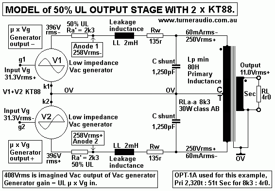
Fig 1 shows 2 x KT88 powering OPT-1A modelled as simply as
possible.
The pair of KT88 could be modelled even more simply as one Vac
generator driving OPT
through Ra 4k6 and with LL = 4mH and load of 8k3 with shunt C =
625pF and all without
a CT. But here I have allowed for class AB to be considered where
each tube cuts off
during part of each wave cycle.
But to keep my explanations simple, the Vac above may be
considered as only class A
without the complex explanation needed for class AB where tubes
switch off during each
1/2 wave cycle. Most ppl use only 1W average from each channel,
and all their listening
is covered by the initial class pure class A with drum beats and
other short lived signals
up to 50W with class AB action.
Fig 1 has Vac across primary = 500Vrms for 30W for RLa-a = 8,300r.
Iac = 60mArms,
and if 30W was all class A the idle Ia in each 1/2 primary =
85mAdc. This would need
2 x KT120 with Ea +400V, for Pda = 34W, or else a quad of EL34 or
6L6GC with each
having Pda = 17W, and sound would be superb.
I have 4r0 as secondary RL which is transformed to anode RLa-a 8k3
between each anode
and the CT is at 0Vac, so each tube has load = 250Vrms / 60mArms =
4.17k.
The primary winding has minimum inductance when Va-a < 5Vrms
where the permeability µ
may be 1,000 with Lp = 80H. But at high Vac shown the µ could be
5,000, and Lp = 400H.
At low Va-a, 80H XLp = 8k3 at 16.5Hz, less than 20Hz and OK. At
high Va-a levels, Lp 400H,
XLp = 41k at 16.5Hz, so at high Vac levels there is extremely low
Iac flow wasted in the
primary inductance.
Without a secondary shown, the effect of LL is shown with 2 x 2mH
series L at each end of
primary. The total LL = 4mH. The shunt C between each anode and 0V
= 1,250pF, so there
is 625pF between each anode.
The exact LCR model changes where tubes change from class A
working to class B for the
part of wave where one tube is cut off.
But for class A as shown, there will be resonance between C
between both anodes and LL
between both anodes. There are in effect two Vac generators in
series driving through total
Ra = 4k6 + 4mH + 625pF.
Fo = 5,035 / sq.rt ( L x C ) with Fo = Hz, 5,305 is a
constant, L is mH, C is uF.
The Fo in this case with 4mH + 625pF = 100.7kHz.
For any network with Vac feeding R + L + C in series to 0V, the
response at C will remain
flat but have -3dB at Fo and then have attenuation at -12dB /
octave where R = XL or XC
at Fo. In this case, XLL for 4mH and XC for 625pF are both = 2k5
at 100.7kHz.
The F response of any OPT without primary or sec load will remain
non peaked at Fo
Ra in series with L and C is equal or higher than XLL or XC at Fo.
But where Ra is less than XLL or XC, there will be a peak at Fo
because the series impedance
of LL + Csh is much lower than either XL or XC at Fo. Welcome to
queer behaviour of L + C
where they are in series or parallel.
Where the OPT is driven by Vac with low source resistance, there
is more Iac through LL
and Csh so the Vac across Csh at Fo can be up to 4 times the input
Vac to the network.
This can be seen if a balanced Vac with low R source was used to
drive the PP OPT.
If the KT88 are connected in triode mode the Ra-a reduces to about
2k4, and response be
slightly peaked, with -3dB at 110kHz. The response of the 1947
Williamson amp with
2 x KT66 triodes with Williamson OPT detailed in RDH4 was
remarkably good and extended
to100kHz.
Use of 10kHz square wave which contains F up to 1MHz harmonics
will often show ringing
more than one frequency with lowest at the Fo for LL and Csh. The
source R for square
wave must be low, say less than 600r for two oppositely phased Vac
from a balanced Vac
source. Almost no DIYers have any such test gear, but in about
1994 I built a balanced Vac
amp with a pair of 6CM5 with choke feed, and driven by a pair of
E280F pentodes and with
plenty of NFB and I get F response that is flat from 2 Hz to 1MHz.
I can get two phases of
1MHz each with Rout = 600r. Such gear then reveals just how bad
many OPTs can be at
F above 8kHz.
Peaks in HF response above 20kHz without any R loading of OPT can
be reduced with
loads at secondary and also with loads across each 1/2 primary.
In many amps, use of GNFB lowers the effective Ra driving the OPT
so the response is
peaked at HF, and often at there are several F peaks and valleys
before the F response
is attenuated at a rate equal to or exceeding 12dB / octave. In
nearly all tube amps the
connection of only 6dB GNFB is enough to cause much HF
oscillation, and a load at sec
may not reduce the oscillation. The amp may also oscillate at
LF.
Therefore the voltage gain of amp input stage MUST be shelved with
networks which
reduce gain below 20Hz and above 20kHz, so that NFB is made most
effective only for
F between 20Hz to 20kHz. This is explained in my numerous pages
giving schematics
for many PP and SE amps.
Zobel networks are shown across secondary and across primary
windings to prevent
any possibility of oscillations at HF which are most likely when
the amp has no speaker
connected or speakers have extremely high Z at HF, or where the
secondary load is a
capacitor. The use of a pure C load between 0.1uF and 0.47uF can
make many tube
amps oscillate at such high levels the output tubes will overheat
and malfunction within
minutes. This was most likely with amps having OPTs with high LL
> 50mH.
Many old tube amps would oscillate at LF and / or at HF if left
turned on without a
speaker. Warnings were given by makers. This was truly horrible
behaviour by makers
who should have made the extra design effort to make their amps
unconditionally stable.
In 1947, Mr David Williamson proved to everyone why a good OPT
with plenty of
interleaving but with low shunt C was highly desirable. Many
brand-name amp makers
initially made OPTs up to the highest standards Williamson
recommended.
But by 1950, many makers were overwhelmed by several factors of
demand for product,
competition with competitors, and higher labour costs that a race
to the bottom followed
with penny pinching accountants allowed to dictate the size,
weight, and schematic of
any amp produced. The Radiotron Designer's Handbook, 4th Ed,
1955 gives excellent
advice on OPT construction details to get wide bandwidth. But very
many manufacturers
ignored ignored much of what was said, because they feared they
would be ruined
financially if they complied with best advice.
The Fo between LL and shunt C should be above 70kHz which requires
both Csh and LL
to both be kept low.
There is usually an ideal number of interleaved P and S sections
for any OPT, and my
pages for OPT design address this by listing many possible
interleaving patterns for OPTs
from 5W to 500W.
The F response of any OPT varies with Vac source resistance and
bandwidth is smallest
where source resistance driving the primary exceeds the nominal
RLa-a, and there is no
sec load connected.
To make fair comparisons of OPTs, the response should always be
tested with nominal
secondary RL connected, and source resistance for Vac driving
primary input is not more
than nominal primary input load.
So all L+C networks including transformers are really only useful
where both the input and
output of such networks have correct "termination resistance". For
OPT-1A with TR =
2,320t : 51t, and designed for nominal 8k3 : 4r0, the secondary
load of 4r0 should be
connected and the source resistance driving the input should not
exceed RLa-a or 8k3.
Where the Vac source R = RLa-a then for middle of the bandwidth
where Lp, LL, Csh have
negligible effects, the OPT-1A with sec load 4r0 has primary
termination R = 8k3 and if Vac
driving it has 8k3 then total primary termination R = 8k3 // 8k3 =
4k15.
it would be "unfair" to publish measured specifications where no
sec load is connected and
Vac source resistance is say 200r from some low Rout sig gene or
say 60k using 2 x KT88
in pure beam tetrode mode.
For example, with no RL at sec, and with Ra-a = 60k, and with Lp
minimum 80H, F1 LF pole
may be 120Hz where XLp = 60k. If Csh = 625pF, F2 = 4.25kHz. In
many amps with pentodes
or tetrodes with screens taken to a fixed B+, no sec load is used,
no gain shelving is used,
and no NFB is used, the response looks most unsatisfactory. But
this does assume the input
driver amp has bandwidth of say 3Hz to 50kHz at least.
The secondary output response looks better when the nominal sec
load is added, and for
OPT with 8k3 : 4r0, Lp min = 80H, expect F1 = 17Hz and F2 at
30kHz. Use of Vac source
with 8k3 should give primary termination R = 4k15 and F1 at 8Hz
and F2 at 60kHz.
The properties of source resistance, C, or L at input or
output of an OPT are transformed
by the ZR. OPT-A has ZR = 2,069 : 1. Consider the OPT-1A without
any sec load. If Vac
source R = 8k3 at primary, it appears as 4r0 at sec where it is
measured mid band where
Lp and LL and Csh have no loading effect. But at say 50Hz, The 80H
of minimum Lp is
measured at sec = 80H / 2,069 = 38mH. Its reactance = 12r1. At
60kHz, 625pF Csh across
primary has reactance = 4,240r, and at sec this would be measured
as 4,240r / 2,069 = 2,05r
and at 60kHz the C = 1.29uF.
If LL at primary = 4mH, its XLL at 60kHz = 1,507r and at sec it
appears as 0.73r, and LL
= 1.93uH.
So at 60kHz, and with primary Vas source 8k3, the OPT sec could be
modelled as Vac
source of 4r0 in series with 1.93uH driving sec output terminal
with 1.29uF to 0V terminal.
What I have said about HF response is a guide for OPT-1A. The real
real behaviour may be
slightly different to the theoretical. With no sec load and source
R < 1k2 at primary, sec
response may be different depending on whether the interleaving
pattern in the OPT is
5P+4S or 4P+5S even though Csh across primary should be the same
for both patterns.
There is never any oscillation in amps without any GNFB. At the
amp output with no NFB,
there are accumulated phase shifts caused by OPT reactives Lp, Csh
and LL, PLUS those
caused by C+R coupling between 2 input stages plus and Miller C
plus any other stray
circuit C or L. In theory, the GNFB reduces high Rout at sec
without NFB to be perhaps
1/10 of the nominal sec load value. But without gain shelving
networks the GNFB will just
convert an audio power amp to be an RF oscillator. So the OPT
response cannot be
specified by the measured response with NFB.
To measure and define the specification for any given OPT, it
should be done without any
GNFB or local cathode FB windings in output stage and with nominal
sec RL, and with
input Vac source R does not exceed nominal RLa-a.
For testing and measuring OPT F response without using tubes
in a circuit or with a voltage
amp producing up to +/- 100Vrms with say 2 x 600r Rout, there is a
simpler way :-
Fig 2. Simplest test rig with basic properties od OPT.
Fig 2 has OPT-1A with one end of Pri to 0V and other live end to
Vac source using sig gene
giving up to 10Vrms and with VR1 to vary Vac source resistance
between the Rout of sig gene
of say 100r to 10k. The value of VR1 can be measured, and Iac =
Vac across VR1 / VR1 value.
VR1 could be 10 x 1k0 x 1W in series and link is used to reduce R
to lower than 10k0.
The secondary should have its 0V end taken to the OPT CT. This
means the relative Vac
between each end of Pri are the same as for the set up of OPT in
an amp, so Ca-a should
be able to be measured without Sec RL, but with VR1 set at 10k0,
and Vac ends of sec
are applied to two channels of CRO set to diff mode. A typical CRO
has 33pF input to each
channel and in this case there is 2.28Vrms that is common to both
channels but 0.1Vrms
difference easily measured with a DMM at 1kHz. This is then
displayed on CRO and as F
is increased the CRO input C should not alter the measurement of
the the network with
10k0 + 625pF which should give -3dB = 25.4kHz.
Without Sec RL, the -3dB point for where XLp = VR1 should be able
to be found without
the input Vac causing any core saturation. If Lp was 80H, and VR1
set to 10k0, expect
= -3dB point at 20Hz where XLp = VR1 = 10k0.
OPT-1A is designed for Va-a = 474Vrms at Fsat at 14Hz and 1.5Tesla
with 27W to RLa-a = 8k3.
If Fsat = 20Hz is allowed, Va-a may be 677Vrms for 55W to 8k3.
With Va-a = say 7Vrms and 20Hz, Bac = 0.016Tesla, and no core
saturation will be seen, but
there may be high distortion due to hysteresis producing reactance
that is non linear at low
levels.
it is possible to set VR1 to 1k0, and distortion should be less on
CRO. Vac may be measured
across 1k0 and across primary at 20Hz and XLp = Vin x 1k0 / Vac
across 1k0.
Lp = XL / ( 6.28 x F ).
If XLp at 20Hz > RLa-a at such very low Vac and F there will be
no problems with low bass
in music because XLp will rise to a maximum of about 5 x minimum
XLp at high Vac at 20Hz
because of the increase of core µ permeability at higher Vac and
hence higher Bac.
Fig 2 above may still be very confusing to many, and a modern
approach is to not bother with
above observations and instead compose a most simple equivalent
circuit for an OPT and enter
details into LTSpice circuit simulation program. This is something
YOU may be able to do, but
unfortunately, the program is so terribly dumb, it cannot just
read my .gif, and confirm with me
what it has read, then work out the F response at "output Vo" and
give phase shift details.
I have never been able to find the time to learn how to use
LTSpice etc because none give
enough comprehensible help to get me started. Programming Nerds
cause much misery......
Fig 3. Very much simplified circuit elements for any OPT
This shows a very simple model for Vac produced by tubes with
their Ra and feeding what
is the basic LCR model for OPT-1A.
Fig 4.
Fig 4 shows the OPT No1 with its Csh appearing at each anode. The
secondary is connected
to 0V at one end and has negligible signal Vac compared to the
primary Vac so sec layers may
be regarded as as earthy wound screens all connected to 0V. At
each of four P-S interfaces
there is 920pF so total C = 3,690pF. But the sum of the C
appearing at the anode is the sum
of the transformed values of C and I calculated 1,227pF is
effective C from each anode to 0V
with Ca-a = 613pF, approx.
Fig 5.
Fig 5 shows the bobbin winding details for one of the larger
output transformers I
have for sale. OP1 has Np 1,496t : 63t Sec for TR = 23.75 : 1, and
ZR = 564 : 1.
If sec = 4r0, then RLa-a = 2,256r.
RwP = TL x Np / ( 44,000 x Cu dia squared ) = 296mm x 1,496
( 44,000 x 0.45mm x 0.45mm )
= 49.7r, say 50r.
Pri loss % = 100% x 50r / ( 50r + 2,256r ) = 2.16% = OK.
For OP1, Afe = 2,700sq.mm. My OPT design says Afe = 300 x
sq.rt Po.
Therefore sq.rt Po = 2,700 / 300 = 9.0, so Po rating = 9.0 x 9.0 =
81W.
For 81W for 2,250r, Va-a = 427Vrms.
At Bac = 1.5Tesla, Fsat = 22.6 x 427Vrms x 10,000 / ( 2,700sq.mm x
1496t x 1.5T ) = 15.9Hz.
This is quite acceptable.
But 2,250r is a very low RLa-a for one pair of EL34, KT88, etc.
2 pairs give RLa-a = 4,500r, each pair makes 41W,
3 pairs give RLa-a = 6750r, each pair make 27W,
4 pairs give RLa-a = 9k0, each pair make 21W.
I think 8 x EL34 would be the best choice of tubes. They will cost
less than 4 x KT88 and do a
better job.
Va-a = 427Vrms, so Va = 214Vrms, or 302Vpk. For each EL34, AB load
min = 9k0 / 4 = 2,250r.
Peak Ia max = 302V / 2,250r = 0.134A. If the UL diode line R =
250r, Ea = 0.134A x 250r = 34V.
If Va pk swing = 302V, the Ea = 302V + 34V = 336Vdc. EL34 Pda+g2
at idle = 20W.
Idle Ia+g2 = 20W / 336V = 60mAdc. Ig2 = 6mAdc, Ia = 56mAdc.
Initial Class A Po = 14W and for 4 pairs = 56W. Idc rating for
primary wire = 2A/sq.mm, so max
continuous Idc could be 318mAdc, but with 4 EL34 Idc = 240mAdc =
OK, but could be reduced
because nobody needs 56W of pure class A. Input power for 8 x EL34
= 160W. Power costs money.
But idle Idc could be reduced 40mAdc per tube and still get the
same class AB Po and get 28W
for initial class A. All this is for 4r0 output load.
Unfortunately, OP1 has 12 x 63t sec windings
which can only be arranged for 12 // 63t for 4r0, or 6 // 126t for
16r0.
If an 8r0 speaker is connected to 126t, RLa-a = 1,125r, so each
EL34 pair has RLa-a 4k5 and you
get 33W at anodes and about 31W at output so 4 pairs give 124W AB1
with first 14W of pure
class A.
RwS for 4r0 = 296mm x 63t / ( 44,000 x 12 x 1.0mm x 1.0mm ) =
0.035r.
For sec RL 4r0, RwS loss % = 100% x 0.0353r / 4.035r = 0.89%,
which is excellent.
At high frequencies, there is a major difference between my OPT-1A
design and OP1.
Because the interleaving pattern = 11P + 12S, there are 10.5 P-S
interfaces on each side
of Pri CT. Nomex insulation = 0.25mm so total static C = 34,902pF.
There is 17,451pF each side of CT and effective C at each anode to
0V = 5,815pF.
The Ca-a = 2,908pF. If RLa-a = 2,250r, then Xc = RLa-a at 24.4kHz
and load for tubes
= 1,597r.
The F response will not be -3dB at 24.4kHz if there are tubes
connected which have
finite Ra which is effectively in parallel to the Ra-a.
Fig 3 above shows OPT-1A driven by a low Rout signal generator
through 8k3 which is
a nominal value for standard OPT specification for any OPT where
tube anode resistance
Ra-a is assumed equal to nominal primary load of RLa-a.
For OP1, there are 8 x EL34, and their Ra-a in pure class A
pentode mode could be 30k
each so Ra-a for a pair = 60k, and for 4 pairs it could be 15k0.
But for 25% UL, each Ra = 4k8, so Ra-a = 9k6 for 2 x EL34 so for 4
pairs Ra-a = 2k4, and
where OP1 has a 4r0 sec load giving RLa-a 2k25, then RLa-a // Ra-a
= 1k16.
Ca-a is in parallel with 1k16. The HF is -3dB at F = 159,000
/ ( 1,160r x 0.00291uF )
= 47kHz. The LL for OP1 is very small, and XLL is effectively in
series with RLa-a but
will have little effect on the -3dB pole calculated.
If EL34 were in triode mode, with Ra of each = 1k3, the Ra-a for 1
pair = 2k6, and for
4 pairs is 650r. RLa-a // Ra-a = 2k25 // 650r = 505r, and HF
response would be 108kHz.
But the LL which is in series with RLa-a may have prevent such a
high -3dB pole.
At low class A levels at 20kHz, it is hard to conclude that the
capacitance could have any
effect on the tubes, and the GNFB would slightly raise input Vac
to EL34 grids to maintain
a level response.
For OP1 driven with 4 pairs EL34, each pair is loaded by 9k0 //
702pF and this is similar to
OPT-1A where I have 3 x KT88 loaded with 8k3 // 625pF.
OP1 has interleaving pattern SPSPSPSPSPSPSPSPSPSPSPS, ie, 12S +
11P.
OP1 would be much better if it had SPPPSPPPSPPPSPPPSPPPS, 6S + 5P.
There can
be 15 layers of primary at 136tpl for Np = 2,040t, Sec could be 6
layers 64tpl, each 2 x 32t.
wound bifilar.
Load matches are 1k8 : 1r8, 4r0, 7r2, 16r0, or 3k6 : 3r6, 8r0,
14r2, 32r0.
Va-a could be higher with lower Fsat. Each P-S interface has
0.51mm Nomex for 1,000pF.
Anode to 0V C = 5,000pF / 3 = 1,666pF, so Ca-a = 833pF, which is
less than 1/3 of the C
for existing OP1.
If RLa-a = 2,250r, XCa-a = RLa-a at 85kHz. The capacitance loading
at 20kHz is negligible,
and I believe this makes the HF sound better.
So, IMHO, OP1 has too much shunt C, but use of many parallel tubes
overcomes the problem.
---------------------------------------------------------------------------------------------------------------------
Leakage inductance cannot be ignored, and for my OPT1A it is about
4mH at primary input.
LL = 0.417 x Np squared x TL x [ ( 2 x n x c ) + a ] / (
1,000,000,000 x n squared x b ) where
LL = leakage inductance in Henry, 0.417 is a constant for all
equations to work, Np = primary turns,
TL = average turn length around bobbin,
2 is a constant because there is an area at each end of a layer
where leakage occurs,
n = number of dielectric gaps, ie, the concentric gaps between
layers of P and S windings.
c = the dielectric gap, ie, the distance between the copper wire
surfaces of P and S windings,
a = height of the finished winding in the bobbin,
b = the traverse width of the winding across the bobbin.
Distances are all in mm!
For OP1,
LL = 0.417 x 1.496kt x 1.496kt x 296 mm x [ ( 2 x 21 x 0.28mm ) +
25mm ] / ( 1,000 x 21 x 21 x 75mm )
= 0.326mH. If the LL is calculated for 1/2 of primary, the
LL in series with each anode = 0.163mH.
The 0.326mH for the whole primary resonates with Ca-a 2908pF to
give
Fo = 5,035 / sq.rt ( 0.326 x 0.00291 ) = 163kHz.
At Fo, XL and XCa-a are both 335r, so for critical damping with Q
< 1, load RLa-a should be 335r, so
the RLa-a load of 2,250r will not damp the resonance much,
especially if the 8 x EL34 have say 15.8%
CFB which reduces pentode Ra-a of 50k to 600r. However, this
series resonance with very low Z
at Fo is so far above the AF band that its effects with GNFB is
negligible if the open loop gain of all
tubes can be reduced to below 1.0 at 163kHz. If OLG < 1.0, the
amp will not oscillate whatever the
phase shift may be. The open loop phase shift may reach -90degrees
well below 163kHz and
-180degrees above 163kHz. If shelving R + C networks between V1
and V2 in amp reduce open loop
gain to below 1.0 where phase shift exceeds -180degrees by say
50kHz, the amp will not oscillate
with GNFB.
An amp using OP1 should give maximum Po between say 500Hz and
1.0kHz where RLa-a = 2k25.
Below 500Hz, full Po should be very nearly stay constant to 20Hz
because XLp is so high and causes
negligible inductive loading. Above 1kHz, the Ca-a loads the amp
so ZLa-a = 2k0 at 12kHz, 1k6 at 24kHz,
1k0 at 48kHz where phase shift is nearly -90 degrees. Beyond
48kHz, I cannot say what phase shift is
because the input tubes add their phase shifts. Above 48kHz the
open loop gain should be less than 1.0
before phase shift reaches -180 degrees, so oscillations seem
fully preventable.
Without any RL at sec, the only load for tubes is primary
inductance Lp and Ca-a in parallel.
At full Po levels with Va-a = 427Vrms, Lp at 20Hz may be 250H. ZLp
= 31k. The core µ may be high,
but L may halve with reducing µ so L at 200Hz = 125H, but XLp =
157k in theory.
Without measuring OP1 very carefully, it is very difficult to
determine parallel Fo between Lp and
The Ca-a.
But If I assume Lp 100H, and Ca-a is known 0.00291uF, Fo = 5,035 /
sq.rt ( 100,000mH x 0.00291uF )
= 295Hz.
At this Fo, resonant Z ( Lp // Ca-a ) should be higher than XLp or
XCa-a, which would both be 185k which
causes very little load change where RLa-a = 2k25. At 1kHz and
above Fo, the XLp will be above 200k,
but XCa-a is 55k, and reducing to 5k5 by 10kHz, and 2k7 by 20kHz,
and nearly equal to RLa-a.
I would much prefer that Ca-a be at least 1/3 of what it is.
With 4r0 load at sec linked for 12 // 63t, the RLa-a of 2.225k
barely changes between 20Hz and 5kHz.
but above 5kHz at full Po you could expect to see increasing THD
and by 20kHz a sine wave would
resemble a triangle wave and and to avoid the slew rate distortion
caused by C loading, the input level
of amp would need to be reduced by maybe -2dB. For little THD at
30kHz, Vo may need to be be -4dB.
But the Vo response for 1/2 full Po at 1kHz can be quite flat from
20Hz to 25kHz with THD only twice the
1kHz levels.
Conclusions.
1. A maximum possible number of interleaved sections exists in
OP1, and it causes shunt C to be too high.
The LL is much lower than it needs to be.
2. OP1 requires a large number of parallel tubes for best results,
8 x EL34, KT66, 6L6GC will be fine.
3. I doubt anyone could tell any difference in sound between
having say 8 x EL34 with OP1 or having
4 x KT88 or 6550 in an OPT for same Po but with with far lower
Ca-a.
In my 300W, I did use more interleaving than in OPT-1A. As the
size of OPT increases, the interleaving
should increase. The shunt C must be kept low so the insulation
thickness must increase.
As the insulation increases, so does LL, so there are a
considerable number of interactive quantities to
be considered. I thus include interleaving pattern tables at my
OPT design pages, and if anyone follows
the many logical steps to design an OPT, they will never be
disappointed.
I can guarantee that the transformers I do have for sale will
certainly handle music well.
OP3 listed at my For-sale pages was used in two 60W SE monobloc
amps each with 6 x 6550 in
parallel with CFB use. Sound is excellent.
Back to output
transformers 2 for sale
Back to Index page