WINDING
OUTPUT TRANSFORMERS.
This page updated July 2017.
This page is about practical winding methods for small volume OPT
production,
and what the DIYer needs to consider.
Images are :-
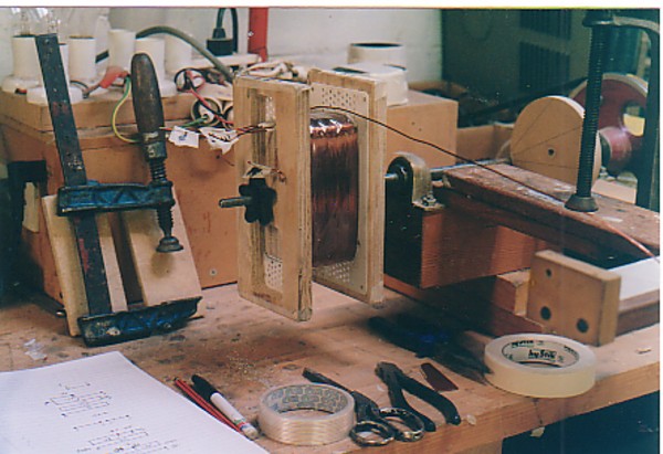
Image 1. Bobbin winding details for OPT No1 mentioned in OPT
transformer theory.
Image 2. Four transformers on a work bench.
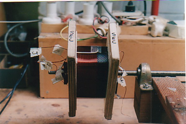
Image 3. Two 300w OPT on bench.
Image 4. 500w OPT on table.
Image 5. Winding lathe with bobbin being wound.
Image 6. Wound bobbin close up.
Image 7. Close up of 300w OPT handmade bobbins on bench.
Winding procedure, varnishing, alternative to varnishing by using
Estapol
7008 during wind up.
Metric winding wire size chart for grade 2 polyester-imide wire
for high
temperature rated motor and transformer windings, for up to about
200C.
-------------------------------------------------------------------------------------------------------
WINDING PRACTICES, POWER and OUTPUT TRANSFORMERS and CHOKES
Many people emailed me for advice for winding OPTs for their own
DIY amplifiers.
I always gave what advice I could, and a few actually succeeded
although many
just gave up because transformer winding is a trade needing
learned and practised skills.
If someone only knows what they read in old books and online, they
will struggle to
make an OPT unless they start by winding a layer wound
choke, and then provide
the time, tools and space for their projects.
The first thing required is a powered lathe. For those
without electricity, a pedal
powered lathe may possibly be OK because the amount of power is
similar to a
treadle powered sewing machine first made before 1920.
The lathe torque needed is sufficient for the thickest wire up
about 2mm dia, but
very little torque is needed for 0.15mm dia wire.
I won't mention a treadle powered lathe again because a motor
driven lathe is much
better because it allows better concentration when using both
hands without having to
turn pedals. But remember that many women sewed fine dresses using
both hands
and the legs to work the treadle!
An electric lathe need only rotate at a maximum of 5 turns per
second, or 300rpm.
The speed must be able to be varied as you wind, and start / stop
action should
never jerk the wire too tight.
I built my own powered lathe to allow use both hands to
handle the wire.
A foot switch on the floor was used to turn mains power on and
off.
My lathe uses some 100mm x 50mm and 100mm x 100mm timber off-cuts
from building
work used to make a firm timber bolted and screwed and glued
chassis. I have a
plywood box with a an electric drill as a motor fixed in box and a
flexible coupling to a
12.7mm dia x 300mm long shaft held to chassis with two ball
bearings in trunnions bolted
to chassis behind the lathe shaft. The electric drill motor is
only maybe 200W type,
with its speed set to low. The electric motor box has insulation
inside and a lid that
fits well and noise is kept low.
The main lathe shaft is plain bright steel bar of 12.7mm dia (
1/2" dia ) and also 300mm
long and has same two trunnion bearings. The steel shaft was easy
to buy, and trunnion
bearings were bought from a tractor spare parts supplier. At one
end of lathe shaft there is
a 200mm dia pulley wheel and the bearings and shaft position was
adjusted so the belt
tension is not tight, but can be flipped off the pulley if needed.
The other end
The timber chassis frame is a U shaped frame, with rear motor box
and shaft about
600mm long then chassis extends forward about 450mm and the lathe
shaft is about
400mm in front of the rear shaft of motor.
The lathe shaft end away from the pulley has a 150mm x 40mm plate
about 5mm thick
welded on to the shaft and exactly square to the shaft. The pulley
belt isn't too tight,
and allows the belt to be sprung off the pulleys if needed when
much unwinding from
a bobbin is attempted because there is no reverse direction
possible on the motor.
There is a speed reduction between the drill motor and lathe shaft
of about 5 to1.
I have a manual turn handle bolted to the 200mm pulley to allow
slow hand turning
which is sometimes required to force wires to be where I want them
at ends of layers,
because, as you will find, wire tends to lay up irregularly at the
beginning and ends of
built up concentric layers.
A 100mm long x 10mm dia threaded rod is also welded to the shaft
beyond the plate so
that a bobbin can be clamped between specially cut out plates of
plywood to allow wires t
o be brought out of the bobbin as the layers are wound on. I use a
few screws in the
ply to hold the long free ends of wires to prevent them being
tangled and yanked which
would ruin a wound bobbin.
I used to count the turns at end of a layer to make sure enough
turns were on but that
was too slow and tedious and prone to mistake, especially with
small dia wire, so I made
a mechanical turn counter using an old automotive odometer
mechanism powered by a
copper clad wooden wheel attached that is exactly 10 times the
shaft dia so that for 1 turn
of the bobbin shaft I get a reading of 1 turn, with a turn being
equal to what was 1/10 of a
mile. By carefully filing down the thick copper wire outside
cladding of the wooden odometer
drive wheel I was able to ensure that for 300 turns of the lathe
shaft the number 300.0
appears with error less than a fraction of a turn.
Before commencing the layered winding with accurately counted
turns, you will have got
your turn counter arranged and checked for accuracy by counting
the turns from one to 300,
and reading what the turn counter says. It should say 300.0 If you
get 295.8, the wheel
diameter against the shaft is too large, so you may have to file
it down. Thus I made mine
with 1.5mm copper wire glued with epoxy around around a plywood
wheel of 124mm dia so
that I could file it down to be 127.0mm, which is 10 times the dia
of the clean bright 12.7mm
dia. I filed the wheel diameter down until I got very accurate
turn counting.
The wheel and counter is mounted on a spring loaded wooden block
so it can be slightly
swung away from the lathe shaft but is otherwise held against the
shaft with the old spring
I found among the many old bits of junk in one of my junk boxes.
This allows me to swing
out the counter and spin it up or down to a whole number of
thousands at the beginning
of a new wind up it make recording the turns easier. If I reverse
wind to undo a mistake,
the turn counter winds backwards automatically and accurately.
I think I spent a day or three building the lathe and it all cost
less than $200 in 1994.
I could not find a second hand coil winding lathe and the new ones
were way too expensive.
Unless I employed someone to use it all the time to make
transformers, the cost of a
commercial winding lathe would not pay for itself.
Nobody I ever knew wants to learn to wind transformers accurately
for a living unless they
gain employment at one of the dwindling number of commercial
winding workshops where
mainly mains transformers are wound repeatedly.
There is no automatic traverse guide or wire tensioning device on
my lathe. Devising an auto
traverse guide that is adjustable for the wire dia used was going
to be very difficult for me to
make. Wire tensioning device was also too hard, so I fixed a hand
rest in front of lathe shaft
to rest my hands on, and fed the wire through bare hands, after a
little practice I was good
with that, creeping wire across the rest and pulling wirer tight
enough so the wire turns
all laying together with no gaps between turns. If I had a crossed
over turn, I could stop,
keep wire tight while I unwound a few turns, the re-wound.
The wire was fed on from spools of wire below the lathe, with
bench leg used for a wooden
dowel axel on which the spool could turn. This way the wire rolls
off the spool and onto the
bobbin without getting twists in the wire which can lead to
tangles and kinks in wire.
I sometimes taped cloth over the wire to damp the action of
wire and to prevent eager wire
loops springing off the spool and tangling or forming a kink in
the wire. You cannot see when
this happens and it pulls tight when the wire feeds up through
hands. Winding must stop,
and kinks must be avoided and gently straightened before
continuing to wind them on a layer.
The hand rest needs to be about 500mm away from the bobbin for
almost all transformers and
chokes, and the leading on of the wire is easiest with this
distance.
Speed control for the motor is primitive but it works.
There is a foot switch for on and
off, and 8 lamp sockets for incandescent lamp globes are mounted
on a nearby wood block so
various numbers of lamp globes or various wattage can be connected
in series with the drive
motor, so that I can get from 1/2 a turn per second to about 5
turns per second. The slight extra
light from the lamps help me see what is happening while lathe
turns. Bright lighting is essential.
The lamps offer series resistance to the motor, and if the wire
tension becomes excessive, and
slows the turning, lamp current increases and they glow brighter
with increased resistance so
they protect the motor against excessive current. It is extremely
primitive, but it works well.
One has to watch very closely so that the wire layers are neat,
flat, and have the right number
of turns, and do not pull down past insulation sheeting at the
ends of layers, and that gaps
between turns do not appear.
Apart from the lathe, you will need :-
A Carefully Calculated design sheet with exactly what is to be
wound with the bobbin details
set out on an A4 page beside the lathe so the turns can be
recorded at the start and finish of
each layer. If you accidentally leave a whole layer of wire out of
the design, the work is quite
useless later. This is likely to happen if you get interrupted in
your processes by visitors, phone
calls, debt collectors, children, or angry demanding wives or over
amorous wives. When you
begin a transformer NOTHING must get in your way.
You will meed cutters, scissors, masking tape, felt
marking pen to identify the
ends of windings.
I found I needed a 20mm x 80mm hard plastic blade, sharpened along
one end and edge to
be an adjust tool when slightly adjusting wires closer when gaps
occur or undoing crossed
over turns. Never ever use a metal penknife or a screw driver or
anything metal to adjust
wire positions on the bobbin.
The insulation must be prepared before winding, enough
estimated and and pre-cut to exact
width between bobbin cheeks. I used a hardwood straight edge about
1M long clamped on
top of the insulation material usually sold on rolls about 900mm
wide. With insulation clamped
tight, a sharp box cutter was used to cut the insulation. this
slow non automated method
allowed me to get the right insulation width.
Tight fitting wire sleeving is used on wires where they
enter and exit bobbin cheeks and
it should be polyester or fibreglass hi-temp woven auto grade
type.
DO NOT USE SHRINK WRAP. Use tight fitting as possible, for 12mm
outside and inside
bobbin.
ONLY use Grade 2 winding wire which is double enamelled
winding wire with high
temperature polyester-imide enamel. It is usually dark brown, and
it is usually impossible
to tin the wire with solder unless you gently scrape off the
enamel with a penknife.
DO NOT use bright coloured polyurethane coated wire which can be
easily tinned with
soldering iron and solder with flux core.
Thin general purpose sticky tape say 20mm wide is useful
where a tap is brought out.
A tap means the winding stops, wire is taped to stop turns
loosening.
A loop of wire say 300mm long is taken out through bobbin over
turns already wound,
and the return wire is taped down to allow continuing turns. The
loop is cut outside
the bobbin and sleeving is pushed on two wire ends from outside to
inside bobbin right
up to where the turn of wire begins to bend to exit the bobbin.
The return wire is taped
to existing turns and bobbin and continuing turns are wound on.
The tap wires may exit
either side of bobbin but MUST have sleeving to prevent pressure
of the winding layers
causing wires to bight into enamel and cause a short circuit.
Try to always use plastic moulded bobbins. But where the
right size is not available
you must make your own. Use two layers of 0.8mm Kraft board well
glued around a timber
mandrel slightly bigger than core S x T. The bobbin cheeks may be
1.6mm fibreglass
sheet cut to size and glued to bobbin base with epoxy ( 5 minute
Araldite is OK ) and all
this is done with timber mandrel clamped tight with bobbin hold
plates on lathe.
You must learn to be accurate, or just fail, and unless you
are correct within 1/2 a
millimetre, you are sloppy and a non craft person. Decide that the
job comes first,
and you have to commit to using a vast amount of time.
Electrical varnishing of all bobbin contents is a difficult
but necessary process so that
wires do not move about on the layers due to high magnetically
induced forces.
Maybe the simplest way is to spray on polyurethane
furniture varnish before and after
each wire layer and then before each insulation is wound around
the winding once, and
taped into position to prevent movement. This must be barnished
before next wire layer.
The sprayed on varnish means wearing a face mask with filter and
having very good
ventilation and. The sprayed varnish will remain fairly soft after
each spray but over days
and weeks it will harden. Alternatively, paint the varnish on as
you go with a brush.
The windings bulge as they are wound. The wound transformer
bobbin should be left
on lathe for 3 days with blocks of plywood clamped to the surfaces
of each side of bobbin
which will be within the winding window of the core. You want to
be able to easily insert
the E+I lams or C-cores without core rubbing hard against the
cover insulation over the
last on winding.
Such varnish softens in heat above 90C but that is unlikely if
your amp has a thermal
cut out or has active protection against excessive Idc from one or
more tubes.
When the transformer is assembled with core, the gaps
if any are set to correct size
and all is bolted up but left loose for more varnishing by soaking
in a vat for an hour.
After the soaking, raise it out of vat and allow to drain for an
hour, then while still wet,
tighten bolts and place in spacers of phenolic plastic sheet all
wet with varnish.
All the wires exiting bobbin cheeks should have labelled tags of
masking tape using pencil
or ink that is not dissolved by varnish. The varnish will air dry
on outside quickly but remain
liquid within. The terminal board may be fixed and all wires taken
to labelled terminals
and with sleeving on. Wire is stripped of enamel with knife, wound
twice around terminal
and soldered. The terminal board may be on the under side of
laminations of core if the
complete transformer is in the final position where potting is
used, so that the terminals
are accessible to underside of chassis volume when transformer is
fixed into position.
After trial and error, you will realise the correct sequence for
all these necessary steps if
you want to make something of high quality.
Half the total labour time for a good pair of 50W mono amps will
be in transformer work.
The total time for the 100W of amplification is equal to 500 times
the factory time for a solid
state PWM amp with maybe 6 x 100W channels for home theatre.
Tube craft is about time.
There are more details to be considered than what I am saying here
but all such details
were always once considered by people who worked in factories in
1960.
You just cannot print an OPT with a 3D printer.
Vacuum impregnation is maybe the best way to varnish and it
involves using special
electrical varnish that does not boil of vaporise in a vacuum at
room temperature.
The transformer is submersed in a vat of varnish below the surface
of varnish, the
vacuum is pulled. The air in voids and cavities in windings will
expand and be removed
in a few minutes, The air pressure is allowed back and it forces
the liquid varnish to seep
into voids. Increasing air pressure to 10 times atmospheric
pressure will help force in varnish
and then pressure is slowly reduced and this should wet all
internal surfaces.
Baking finished OPT after all varnishing and assembly.
If the transformer has brushed on furniture varnish, it MUST
NOT be baked. Over time the
polyurethane varnish will harden.
IF the transformer has electrical varnish brushed on, or vacuum
impregnated it may be
baked by raising its temperature slowly to 125C for 4 hours and
allowing it to slowly cool.
So a temperature controlled oven is needed. The oven may need to
go a bit higher, but you
don't want to raise any part of the wound item to above 125C.
The alternative to electrical varnish, vacuum tank, vacuum pump
and oven heating is to
use Estapol 7008 polyurethane epoxy two pack floor coating. This
is rugged stuff, but
it is a 100% Royal Pain in Arse to apply while brushing on while
winding because it gets
everywhere, is sticky, and you need a pot of metholated spirits
and cloth to keep wiping it
off hands or gloves and the fumes are toxic. I did a few OPT like
this. The finished bobbins
wre a solid block and the transformers functioned flawlessly.
To achieve Great Tube Audio, patience, diligence, willingness,
time, tools, intelligence are
all needed plus a fanatic belief in doing it right or not at all.
Before winding a PT or OPT, wind a choke or two, or three 2 with
neat flat layers of wire
with 0.05mm insulation between layers that are varnished while
winding. It is impossible for
anyone to expect to master the trade of transformer winding in 2
hours.
Tips on winding.
The first few layers wound on the bobbin are the most difficult
because the wire bends 90
4 times per turn to get around the rectangular bobbin shape. i
often glued on a 3mm sheet
of plastic at top and bottom of bobbin base, then filed the
plastic and bobbin to give a
minimum bend radius of wire = 5mm. This made it easier and faster
to wind layers on
without getting crossed over wires and gaps between turns.
For a handmade DIY bobbin, the wooden mandrel former must
have an internal maximum
height about 5mm more than the stack of laminations to be used,
and with rounded corners.
I used 0.8mm electrical grade cardboard strip cut to just the
right width wound twice around
the mandrel and glued with wood glue and held tight with scrap
wire turns until glue cured.
The two layers of 0.8mm thick cardboard ( and 0.8mm is a common
size ) will keep the wires
at least 1.6mm away from the core, and when saturated with varnish
the cardboard will resist
at least 4,000Vdc easily.
When the glue has set, the wire clamp is removed, and the mandrel
and bobbin base around
it is used to mark the holes in bobbin cheeks. I used 1.6mm or 2
mm thick fibreglass sheeting
for each bobbin cheek plate. It is very carefully cut to size with
a hole to take the end of the
cardboard tube. Holes are drilled to allow wires to come out
wherever they
need to be, but to ensure there is always an available exit hole
for a wire adjacent to a layer
end or for a tapping, I drill plenty of 3mm holes in the bobbin
side to allow wires to exit. I don't
use slots because it weakens the bobbin cheek flange. In addition
to the bobbin cheeks, plates
of at least 12mm plywood are cut and drilled to provide support
for the bobbin cheeks, and have
13mm holes for the lathe shaft. One plate is placed on the shaft,
then the mandrel with cardboard
tube is placed on the shaft, then the two cut out bobbin cheeks,
with some epoxy glue to
hold them to the cardboard tube.
All this is done to ensure the cheeks of bobbin are at 90 degrees
to shaft and the bobbin
will turn true or else it becomes difficult to get neat flat wire
layers.
The bobbin cheeks are pressed outwards against the ply plates
before the glue sets.
Don't use excessive glue or allow excessive glue to glue the ply
plates to the bobbin; you do
want to be able to pull the assembly apart later, but you want the
cheeks to remain well glued
to the bobbin base.
Applying glue so it goes only where you want it is very important.
So the surfaces to be glued
both need to be wet lightly, and the easy sliding fit will be
filled with glue. I cannot stress how
important it is to work square level and to +/- 0.25mm tolerances
so that when you are ready
to wind the assembly will turn true without wobble.
Before starting to wind, remove the the glued up bobbin from the
shaft, remove the wood
mandrel carefully, and try some laminations, there should be 1mm
clearance between cardboard
centre tube and core, and between tops of bobbin cheeks, and Es
should be able to touch the
I with 1/2 a mm clearance. Obviously, such manufacture is the work
of a practised craftsman
if it is to turn out right. To do it well you will need a good
drill, drill set, and jig saw, clamps,
and few other tools.
Layer Winding a choke.
To practice skills BEFORE you attemps a PT or OPT, you must use
neat layer winding with
0.05mm insulation between layers wire which may only be 0.3mm oa
dia. If the bobbin width
between cheeks = 33.1mm then you may get turns per layer =
0.97 x Bww / oa dia.
For 0.3mm oa dia, tpl = 0.97 x 33.1mm / 0.30mm = 107.02 tpl. Omit
the fraction of a turn, so 107tpl.
the 0.97 factor allows for some small gaps between turns that you
will find impossible to avoid.
The layers should be neat and flat for the full bobbin width. If
window size = L38.1mm x 12.7mm,
height of bobbin contents should not exceed 0.8 x H = 0.8 x 12.7mm
= 10.16mm, so you may get
number of layers = Max allowed height / ( oa wire dia +
insulation ) = 10.16 / ( 0.3mm + 0.05mm )
= 29.03 and omit fractions of a layer = 29 layers. This would give
total turns = 29 x 107tpl = 3,103t.
If the core is say T25mm x S25mm, this winding would be fine choke
to use for CLC filter for 75mAdc
max for 2 x EL84.
Random winding a choke.
If no insulation is used, and wire is less than 0.5mm oa dia, the
bobbin may be filled without layers
of insulation and wires are wound on by slowly allowing traversing
the width of bobbin without
worrying about crossed over turns which will be at very shallow
angles of less than 2 degrees.
Wire is allowed to flow on where it likes, and the height of wire
will vary and wire will tend to
fill valleys as it winds on. Varnish is painted on after every 100
turns and it ends up soaking all
turns. This is called "random winding", and when nearing the
wanted winding height you may let
turns linger at valleys so you end up with winding height max =
0.8 x Core H.
Random winding has been used since people began winding chokes in
about 1869. But in old
radios in 1930s before permanent magnets were manufactured, the
mild steel magnet core in
speakers had a coil with perhaps 2,000+ turns of 0.3mm dia wire
called a "field coil". The anode
Ia for all tubes was often about 50mAdc which was enough to get a
nice strong magnetic field in
the concentric gap of about 2mm for the voice coil. Many field
coils wound in 1935 survive to
present day, and the field coil acted as a choke for CLC filtering
of the B+. The enamel in 1935
was not as tough as for 2018, but the random method worked OK, so
it sure will work with good
magnet winding wire in 2018.
But the random winding method usually gives a slightly lower
number of turns for a given bobbin
than layer winding because the there is an average gap around each
wire that is larger than for
layer winding, because wires lay irregularly. But the choke will
work fine.
The shallow angles of wire crossings is tolerated where wire
tension is high enough but not too high.
High wire tension means the build up of pressure on wire below the
top means all crossed over
turns have high force. Just as long as the wire does not appear
loose as you wind, the tension is OK.
Winding 0.15mm dia wire is very delicate operation because the
wire will break so easily. If a wire
break occurs, stop winding, tape existing turns to prevent turns
springing loose, remove enamel
with fine sand paper and solder a join and put woven sleeving over
the join, then keep winding -
with more care.
It is precision work. With and OPT, the insulation may be 0.05mm
between primary layers with
have the same +Vdc.
But between Pri and Sec layers, insulation will be between say
0.2mm and 0.8mm, perhaps
polyester, and stiffer and more difficult to handle.
Well cut strips of insulation ensures you get insulation which fit
neatly between the bobbin cheeks,
and where it must be to prevent thin Pri turns which may be at
+600Vdc pulling down past the
insulation onto a Sec layer which is at 0Vdc. This tempts getting
an arc.
OPT design should always allow for two turns less than
theoretically possible for wire under
0.6mm. The in-going and out-going wire entry points should be
carefully planned so to allow easy
terminations after completion. Usually this means that one side of
the bobbin is devoted to
primaries, the other to secondaries. This gives no awkward 1/2
turns added anywhere, although
with large power transformers a half turn may have to be allowed
so the correct heater voltage
is obtained from the few turns of thick wire involved.
But with a choke winding, there is just one side for the in wire
and out wire. Always start with
sleeve insulation on the in wire so it projects 25mm into the
bobbin wind area, with 25mm outside.
Allow 200mm of loose wire end outside the bobbin and wind around a
screw in the holder plates,
and watch that any wire ends cannot get tangled or gripped in
stationery gaps in bearing trunnions
etc so thus avoiding snapping a lead out wire and completely
ruining a winding.
Use a choke wire size that will later be useful for an OPT primary
say 0.4mm dia. With neat layer
by layer winding, commence winding slowly. Soon the wires will try
to cross over each other or
you get get gaps. Stop, unwind crossed turns, and/or adjust the
few turns together closely with
the plastic blade you have. It is better than a thumbnail. After
some time you will know how to
guide the wire to minimize gaps and crossed turns and to be fast
about it all.
Check that a winding that appears to have no gaps between turns
does not have any. Often you
will find you need to push wires to one side of bobbin with your
plastic blade and you will find
the room for the 2 or 3 more turns you want.
Unlike a choke where the turns per layer may vary, an OPT needs
the right number of turns on
every layer.
Where 0.05mm insulation is placed on, have ends overlap 10mm in an
area which is not covered
by iron when it is inserted. Cut off the spare insulation with
scissors, and tape the insulation
overlap tightly. Consecutive overlaps will increase the height of
the winding to more than allowed
height. But all is well if the resulting extra height is outside
the core.
After a few chokes and OPTs, and if you remain sane, you begin to
know just how many turns per
layer you should put on and how important it is to make bobbins
with parallel flange cheeks,
and to cut the insulation correctly, and to never to rush a
winding project.
I found I could make a couple of chokes a day, but making an OPT
took much more time and
OPT-1A below might take a day to wind, another to assemble and
solder a terminal board.
Crossed turns in layer wound coils are prone to high pressure
points which lead to short circuited
turns and early transformer failure. If a shorted turn or turns
occur, the inductance of the complete
choke or OPT is reduced dramatically, leading to a filter choke
with little inductance that does not filter,
or to an OPT with severe bass response problems and probable
destruction of the output tubes.
When an OPT fails in an expensive amplifier it is a real problem
because it may be difficult to
re-create a spare made to a one off design in 10 years' time. So
hence the OPT must be wound
with great care, and used in amplifiers with active protection
measures against excessive tube
currents which may overheat thin wire primary windings and power
supply choke windings leading
to shorted turns due to heat softened insulation. The step from
winding layered choke windings
to an OPT is not a huge step but then you have to learn about
having maybe 30 ends of windings
and taps to deal with.
That becomes easy as you learn that 30 connections means that you
have 30+ wire ends to cope
with so you mark each one with masking tape and label it with a
pen so you know where you are
as you go.
See the Image 1 below for the way to draw up the winding details
to allow the easy winding of OPT.
Image 1.
For the above OPT, when you start winding, set the turn counter at
zero and begin with the
primary at anode 2 at left bottom of the diagram sketch, and label
the wire "1" and proceed
left to right and when the layer is finished, tape the wire to the
side of the bobbin holder
temporarily while a layer of accurately precut 0.05 polyester
sheet is wound around the layer
and taped into place with a small piece of thin adhesive tape. Use
tight fitting woven polyester
sleeving for 20mm inside bobbin and 20mm outside, so you need 40mm
lengths of sleeving.
Proceed with the next layer. Before going right across this time
from right to left, stop to
remove the tape holding the 0.05mm insulation in place and
continue to then complete the
second layer to connection labelled "2" which is brought out
through a hole in the bobbin
cheek and wound around a screw head in the bobbin holder.
Easiest effective varnishing is to paint polyuretane varnish on
before and after each wire
layer and to insualtion layer before placing it over a wound
layer.
This will slowly harden, and you won't need to bake the finished
item.
It is essential that wire not be allowed to slacken off at any
point in the winding process
and it must be kept tight at all times. Removing the small tape to
hold the ends of insulation
sheets prevents a bulge developing after many such tape layers
during the wind up.
Always overlap the insulation ends 10mm and locate the overlap
adjacent to where
wire enters and leaves the bobbin lest the bulges from overlapping
builds up the
height of the winding too greatly to be able to insert the E
laminations.
The process of adding layers of wire and insulation proceeds
upwards as shown above.
At the end of each layer, write down the turn number reached and
make sure the required
number of turns is achieved in each layer. Having 0.05mm
insulation between each P
layer which is usually fine wire between 0.3mm and 0.6mm dia makes
it easier to adjust
groups of turns together with a plastic thumb tool so that gaps
between turns are avoided,
and all turns are pushed up close together all around the bobbin.
No gaps means you
should achieve the right number of turns in each layer.
Be prepared to find the wire seems to have a mind of its own and
gaps and crossed turns
may still occur, especially in he first 1/3 of the wind up where
the wire has to bend sharply
around the rectangular bobbin which causes it to easily cross over
other turns or develop
a gap, and be prepared to stop, wind backwards a few turns, adjust
a gap out, adjust a
crossed turn out, and re-proceed without tangling or kinking the
wire. One needs to be alert.
In the above OPT where any taps in the primary have been designed
to occur at the end
of a layer, the layer end is brought out by taping a wire down
along a layer, cutting the
wire off the spool to allow say 200mm of wire through the bobbin
cheek to a ready screw
in the bobbin holder.
Where there are taps or ends of windings are brought out from
somewhere within a layer
of wire, ie, for secondary connections to ends of windings G-H,
I-J, K-L, the inner wires
to H, I, J, K will all have to exit across windings already wound
so are treated ats taps
so fibre sleeving is placed on such a lead outs to stop the
crossed wires crushing together
to form a short. There will be a return wire treated similarly so
the winding can continue.
Thin adhesive tape is used to secure such wire lead outs as the
subsections of secondary
layers are wound on.
The best way to wind the final Sec layer G-H, I-J, K-L is to wind
three windings each
1/3 of the turns per layer in what is called trifilar winding.
G-H is wound on from one cheek to the other, with gaps between
wire of about 2 wire
diameters. I-J is wound on similarly with wire within gaps of G-H.
Final winding of K-L is
wound on between whatever gaps there are, and with some adjustment
with your plastic
blade, you can get the layer filled without gaps between any
wires. G+I+K ends are from
one side of bobbin and H+J+L are from other side. There are thus
no connections to taps
between bobbin cheeks. The arrangement of the 3 windings will be
the same on a terminal
board.
When a bobbin has been fully wound, the wires will tend to try to
bulge out further than will
allow the iron to fit into the bobbin. At completion of the
wind-up a 0.2mm layer polyester is
wound over the last layer and taped up. I use a pair of wooden
blocks cut to fit tight between
the bobbin cheeks but overlapping the winding, and cramp them
tightly with a G cramp to
bend the wires flatter. This normally works to reduce bulge enough
to get the iron into
the bobbin without interference if the calculated winding height
of wires and insulation is
less than 0.8 x the window height of the laminations.
If calculated height is more than 0.8 x lamination window height,
it may be very difficult to
insert the laminations, so it pays to get the design right.
If there is any spare room between iron and wound bobbin it is
filled by sliding in tightly
fitting scrap plastic cut from phenolic kitchen bench laminate
which is dense, tough, and
high temp resistant as well as a good insulation material.
When I finished winding, I will have an OPT bobbin with many wires
wound around holding
screws in the lathe plates. These wires are all carefully
unwound off the screws, and gathered together to allow removal of
the plywood plates and
bobbin off the lathe without yanking any wires so tight that a
break could happen.
Never force anything.
The Es and Is of laminations should be arranged in piles ready for
insertion as soon as the
bobbin is removed and the mandrel carefully tapped out of the
centre of the wound bobbin
which is fragile, and may try to bulge and spring apart if not
"enclosed" with iron.
There is nothing so boring as stacking in the E+I laminations. It
is all too easy to get the
correct sequence slightly muddled with an E leg under another E
leg from the opposite
direction or one I lamination short, or one too many. This won't
make much difference to
performance but it looks terrible, and I have seem many factory
made PT and OPT where
it was obvious the workers had got drunk the night before. DO NOT
attempt to be a good
amp maker if you are addicted to alcohol.
Check the layers of lams as you proceed each 5mm in height, and
redo where mistakes
occur. In many factories, they used machines to stack E and I to
bobbins, but these cost
money, and the DIYer can't afford such things.
Have the clamping yokes, taped up insulated bolts, insulated
washers, and nuts all
ready for assembly. When assembled, tap up the E+I lams to make
the joins gapless
and the stack looks plumb and square as the bolts are tightened.
When assembled, the
bobbin will feel a little loose in the core due to clearances.
Place phenolic scrap plastic
pressed in tight to eliminate easy movement and make sure the last
layer wound on is
well clear of the core.
At this point the circuit boards for terminations should be wired
or bolted to the outside
of the transformer coils so that they are well held to the bobbin
cheeks with wood blockings
or brackets. The terminals can be turrets but I sometimes use
plywood with small brass
screws, say No 4 gauge x 1/2" or 12mm long. These are available
from most hardware
stores as cupboard hinge screws. Brass plated steel screws are OK.
Where the transformer is potted, a flat phenolic of fibreglass
heat resistant board can
be placed over the end of the lams with rows of turrets or screws
arranged to face into
the chassis area when the item is mounted on the chassis. Exact
details can be chosen
by copying well made OPTs buy more serious suppliers. I never use
flying leads of different
colours; usually there are far too many terminations on my OPTs to
be able to do that
and a terminal board is necessary with a removable box screwed
down over the transformer.
For DIYers, I don't recommend vacuum varnishing because its just
too hard to get right
at home. I tried, with vacuum pump and vacuum tank I made but the
varnish tended to boil
so fumes got into the vaccum pump where it condensed and the pump
piston became ruined.
But the vacuum pump I used was a second hand fridge compressor run
backwards, they
easily pull a 95% vacuum, good enough.
There is never anyone nearby who does vacuum impregnation of
anything; there used to be
specialists, but they are gone.
Soaking and OPT or PT or choke in a vat of varnish for 24 hours is
unreliable. It works on
for a motor armature, but not well for a transformer.
Electrical varnishes can require heat to make them become solid. I
used an old frypan with
an extended lid, and the temperature
control is not to bad. But it may take several hours to make sure
the whole transformer is
raised to a usual wanted 125C, Using an old blanket to cover the
frypan out in the yard to
escape the fumes and keep the heat in is a good idea.
It takes time work out what setting of the temperature dial to use
to get an iron transformer
up to the temperature wanted to make the varnish cure properly so
that the temperature
was uniform within the tranny.
The cost of frypan and other bits and pieces was under $50.
During baking, the varnish solvent is expelled by the heat and any
tiny unfilled area will be
at least wetted with varnish, and some air cavities are fine, and
nothing to worry about.
Waxing was often used in old transformers, and was applied by
soaking the transformer
immersed in a vat of wax kept at 90C for a couple of hours with
the transformer placed so air
can easily rise and bubbles can escape from the many holes drilled
in the cheeks of the bobbin,
with cheeks kept horizontal to avoid air locks.
Wax is drawn in by capillary action. A vacuum isn't needed and
would boil the wax. I once used
candle wax but its melting point at at 50C is too low. I soon
found puddles of wax under trannies
on hot summer days.
There are no waxes I know of with high melting points.
Shellac was also used which you may assume would set solid over
time.
But for chokes, spray on varnish is good if applied for each 3mm
rise in wire height in bobbin.
In OPTs, the best non-vacuum and non-bake varnish I used was 2
pack epoxy floor varnish
with 8 hour pot life. It is painted on before and after each layer
of wire liberally, so before and
after each insulation layer. The winding work then becomes toxic
because of fumes and the
mixture runs all over the bench and you get hands covered in
sticky goo, probably toxic, and
needing to be constantly be cleaned off with metho. When the
bobbin is completed, the
clamps are applied to the bobbin while on the lathe to reduce the
bulge. In this process,
the excess mixture runs out on bench and the therapeutic joy of
winding a good OPT
turns into a Royal PIA. The clamps are removed 30 hours later and
bobbin extracted from
the lathe and you have a wound bobbin that is solid all the way
through.
In August 2006 I wound a pair of OPTs for a pair of SET amps using
845 tubes.
I trialled the use of polyurethane two pack floor varnish instead
of using electrical varnish.
The product here is known as Wattyl Estapol Polyurethane 7008, and
is available in
1/2 Litre or 1L etc cans of part A and part B.
If you don't complete a wind-up within say 6 hours, STOP, clamp
the bulge down and record
the turns and leave it for 2 days at least before continuing. So
that when the curing of the
polyurethane occurs over the next two days the wind-up will have
any bulge removed before
continuing. If you don't clamp up the wind-up then the
polyurethane will harden and you will
never be able to compress the winding later. When finishing to
move again in two days,
always finish after an insulation layer and don't paint over it
with polyurethane before the
clamping blocks are used. Don't disturb the clamped bobbin during
the two days; the
polyurethane fractures easily while 1/2 way along the curing time.
The very smelly fumes given off by liquid Estapol 7008 could be
toxic to some people or
cause an allergic reaction. Skin damage could also occur if not
cleaned off immediately.
A well ventilated work place is essential and an anti chemical
fume face mask recommended.
Gloves will make you very clumsy, so be careful how you apply the
material.
Practice makes perfect.
The effect of such good varnishing usually increases shunt
capacitance +10% because air
voids are filled with gunk that has dielectric constant of maybe
4.
Potting OPT
The noise of an OPT is not noticed in a listening room with sound
from speakers. But with a
dummy R load, OPTs howl quite loudly during testing, even with a
well varnished OPT.
Potting much reduces the noise and best potting compounds harden
to become a hard
rubber that bonds well to steel side and top of a pot.
Special potting mix that forms a kind of rubber is expensive, but
quite good. The pot is
upside down with transformer bolted in with 5mm gap between core
and pot and liquid mix
is simply poured in, and left to cure a day. Make sure this
operation is planned so terminals
are not submerged.
I also found that well baked dry fine washed sand could be poured
in around a transformer
and pot well tapped to compact the sand as much as possible. Pot
is upside down while filling
with sand. Sand is kept 15mm below max level and then sprayed with
cheap varnish to seal the
surface. After a day, a small amount of fibreglass resin is poured
in to make a seal to stop sand
running out. This was cheap, and worked very well.
If ever the transformer needs tobe removed from pot, the 15mm cap
of resin is easy to chip
out with hammer and chisel, and sand pours out for re-use.
I also tried roof pitch for a potting compound which is
indescribably messy and smelly and
smoky when it becomes liquid enough at 200C to pour in around a
varnished transformer.
The pot and transformer should be pre-warmed before a pour in.
Roof pitch is a coal by
product and is good on roofs where temp may reach 65C. Road pitch
melts at 50C, is
easier to use, but is best mixed with sand. The fibreglass resin
with sand is The Best for
DIYer.
Quad-II amps have a type of pitch which seems to have a type of
wax content which makes
the compound have a melting point between pure wax and pitch. But
a failing KT66 would
cause a PT to overheat and expel pitch around the transformer pot
on chassis - sure evidence
the amp had overheated. This compound remains super sticky, and
damps anything loose,
but can make a mess.
There MUST be active protection against bias failures in all new
tube amps to prevent
damage to power and output transformers because tube saturation
from bias failure may
not cause a fuse to blow!
If a transformer is faulty, and needs to be re-wound, and if
potted with epoxy and varnished
within it is more difficult to remove the transformer from its pot
and strip it apart for the iron
which is re-usable. I found the easiest way to strip a transformer
is to place in a small wood
fire for just long enough so that all the resin, epoxy or pitch is
melted and burned away.
The potted item should be burnt in a small fire so heating it
slow, and the item won't explode
by too rapid heating. But this activity is impossible in an
apartment block. I have a fire place
in my house that is far enough away from neighbours to avoid being
a smelly nuisance.
I would not heat a potted transformer if I thought the inner
materials would not just melt out
or exude gasses easily. You must avoid explosions. When the
transformer falls from the pot
when stirring it with a poker in the fire, the core with winding
can be pushed into the fire
further to heat it till just red, then allow it to cool over
night. Next day the bolts and wire c
an be sawn off with an angle grinder and the iron is all there for
re-use, and unaffected by
the slight additional annealing.
The pot may be worse for wear, and may need panel beating or
copying. I once roasted a
wheel barrow full of old fused or shorted chokes and transformers
in 2003, and had a stock
of hard to get laminations in many sizes for re-use in filter
chokes. There was some GOSS
lams in among the lot and the µ of the iron was no different after
the firing than before it.
Winding mains transformers is subject to National Safety
Regulations laid out in the National
Standard Codes of what ever country you find yourself within and
these should all be carefully
adhered to before winding anything that is connected to the mains.
Regardless of where you
get your information from, if you wind a mains transformer and it
causes a shock to somebody
then don't blame anyone but yourself, because you wound it, not
me. The legal systems of
most countries will blame you, and nobody else.
The main requirement of a mains transformer from the Authorities
point of view is ISOLATION,
and SAFETY and to achieve good isolation a vertically divided
bobbin is the surest way.
The mains primary is designed to fill half the bobbin on one side,
and the secondaries will
fill the other side. Many mains transformers are wound this way
but they often use random
windings everywhere which is poor quality when one considers that
a mains transformer is
permitted to have a T rise of 25C above ambient. The 25C rise
means that a power transformer
will be 50C where ambient temperature is 25C and you cannot keep a
hand on the transformer.
RDH4 speaks of max T rise 40C which is way too high, which means a
transformer could be
70C on a hot day. You don't want anything in an amp over 50C
except the tubes.
Having a PT rise +30C each time the amp is used is a heat cycle
which causes copper
to expand and more slightly and the heat slightly softens
insulation. I found layer wound
PTs with paper insulation wound in 1930s in old radios lasted to
the present day, despite
the 20C rise in T. The core material used was low µ, maybe only
2,000, and core losses
were very high, so the well made PTs in old radios had more than
twice the turns per volt
of anything wound now using GOSS. So the core heating was avoided
by just using enough
iron and lots of turns, so a 30W PT of 1935 was the same size as a
100W PT wound last
week. In many old radios, I removed the fragile old PT and soaked
it in varnish and over
time it hardened and it was ready for the next 70 years.
High T-rise can destroy random windings because of the many
crossed over turns and
localized pressure points on wire insulation which tends to crush
to cause shorted turns
especially during a fault event when the tranny may have a
temporary T rise of much
more than 40C.
I wound all my mains transformers with GOSS and with B = 0.9Tesla
max with generous
current rating for wire in neat layered windings so T-rise
is less than 10C above ambient,
and the transformer is never highly stressed, and unlikely to ever
fail during the next 50 years.
I won't be around to repair any of my work.
Image 2.
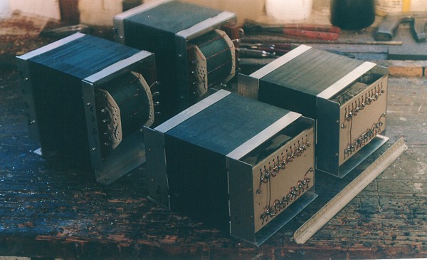
A batch of power and output transformers for 300W amps on the
bench.
The clamping yokes are made from aluminium angles.
The sizes can be estimated by the 300mm long ruler to the right
side.
The two OPTs near the ruler have boards to terminate the ends of
the 12
separate secondary windings to get waste-free load matching.
Image 3.
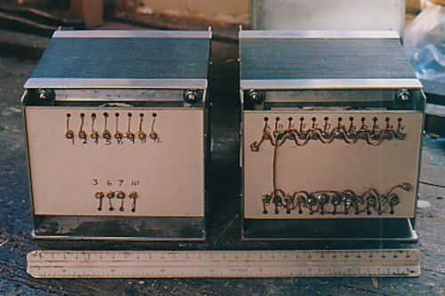
Another view of the primary and secondary boards for the 300W OPT.
Image 4.
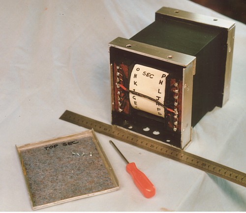
In this 500W OPT I have 3mm thick aluminium angle yokes with
hardwood blocks
with brass screws for the terminations to P and S windings, P and
one end and S
at the other. The OPT sizes can be estimated by the centimetre
ruler, and its used
wasteless E+I, T50mm x S120mm to suit 12 x KT88 / 6550 etc.
Weight was about 16Kg.
Image 5.
This shows the bobbin of 300W amp OPT bobbin being wound on the
home built
winding lathe.
Behind the G-clamp is a box with the electric drill used for the
drive power with lamp
sockets on top for varying the motor speed. The bobbin was hand
made and you can
see the plywood bobbin clamping plates with a large plastic
handled nut that tightens
the assembly on the drive shaft. Just above the roll of masking
tape is a hand rest
for resting hands while feeding wire to the bobbin.
Incandescent lamps are not now much made, because compact
fluoroescent lamps have
become law, so motor control speed may have to be with switched
resistors.
You could also try a Variac.
Image 6.
It is a messy process to wind transformers. This shows a tap being
brought out from
a 48 turn Secondary winding on a 300W OPT bobbin.
There is fibreglass sleeving and covering tape to keep the last
wound turns taught
and the tap in position while the rest of the layer is completed
over the black coloured
insulation material.
Image 7.
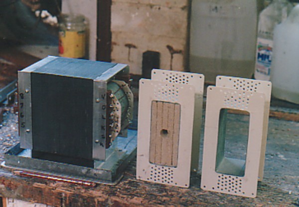
Here is a close up of the 300W amp power transformer with the two
hand made
bobbins for the OPTs showing the timber mandrel inserted into one
bobbin.
The mandrel was made using 5 glued layers of pine particle
board,but plywood
or MDF is also OK. The empty bobbin has grey electrical cardboard
former and
you can see the white fibreglass cheek plates and all the holes to
allow the wires
to enter or leave at whatever height is needed.
METRIC WINDING WIRE SIZE CHART
The metric winding wire sizes were kindly given to me by a local
Sydney wire and
transformer parts supplier,
Blackburn Electric Wires Pty. Ltd, 55 Garema Circuit, Kingsgrove,
NSW 2208.
Ph. (02) 9750.3133 Fax. (02) 9759.0245
They did not appear to have a website but were VERY good to deal
with by mail order.
They gave me 3 charts, all with same wire sizes and with 3 wire
grades. Grade 1 had thin
enamel low temp rating, and is unsuitable for any wound
transformers. Grade 3 had extra
thick enamel for where there is a high Vdc difference between
turns in the same winding,
such as a bifilar wound primaries for McIntosh OPT. Grade 3 was
difficult to obtain.
Grade 2 was easy to obtain and is perfectly suited to all OPT
except McIntosh. Grade 2
which was the main grade stocked by my supplier because it is used
by 99% of transformer
and motor winders where there is high temperature and
stressful industrial applications.
The range of sizes shown are not all obtainable off the shelf, and
to get some sizes there
could be a month delay. So I sometimes had to design around the
wire size available,
without compromising design principles.
Anyone not used to measuring in millimetres should get used to
metric because here the
diameter measurement matters more than the wire gauge. Wire gauges
are AWG, SWG,
BS, all very confusing, and I don't have conversion charts so if
you work in gauges and
inches and feet, provide your own solutions. You MUST have a an
accurate micrometer
to confirm that the size is correct.
To Educational and DIY Directory
To Index Page