40 WATT CLASS B AMP.
In 2005 I had a job to fix an "energy transducer" produced by
James B Lansing in about 1959.
The energy transducer was just a two channel amplifier. It was
originally full of germanium transistors
and many were fused.
If ever there will be a bunch of electronics that won't be missed
it will be all the junk with germanium
which lasted on the scene between about 1954 and 1960.
The resistors and capacitors of that era also were often very
poor, making all the gear with germanium
devices even less worth collecting.
The first transistors were point contact germanium items with
horrific characteristics, and makers of tubes
chuckled about then since they were such poor performers.
But production increased and they weaseled their way into
countless small radios to give us inferior sound
quality that the poor could afford and carry around in their
pockets.
The germanium transistors were very prone to easy failure from
heat and had poor linearity and had current
leakage and noise problems.
In about 1960, the bipolar junction transistors were made using
silicon and with a new heat process and
suddenly it was all over for germanium AND vacuum tubes because
the silicon was thermally much more
rugged than the germanium, and perhaps even better sounding.
The current linearity of the new silicon based bjt wonders was a
lot better and leakage currents were not a
problem and soldering them was easy without having to use heat
sinks clipped to the leads while soldering.
The world suddenly got a heck of a lot more cheap electronics, but
no better musicality in amplifiers.
The early JBL "energy transducer" was merely a 30W per channel
stereo amp for an organ and speaker
console a guy has in Melbourne.
I removed all the germanium based circuitry and old R&C parts
and filed them in the rubbish bin.
The new circuit I used is as follows :-
Fig 1.
The circuit uses the original power transformer with CT secondary
to produce +/- 27Vdc rails with a bridge of diodes.
The arrangement of Q7&Q8 as darlington pairs to drive the
Q9&Q10 effectively give the output emitter followers
stage a high base input resistance at Q7&Q8 because they are
effectively connected as darlington triples. Therefore the
gain of the VAS stage Q4 + Q5 is not disturbed by input resistance
variations of the output stage. The amp continues to
make nice organ music.
But hey, give me a Hammond with a tube amp if you want the best
sound!
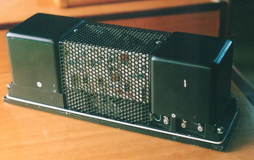
Fig 2
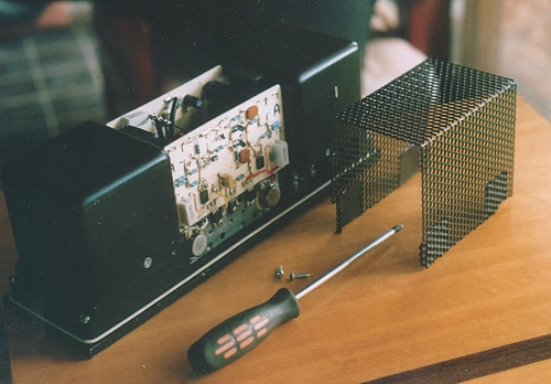
I made the perforated steel cover which slots into position at the
bottom and is firmly held by two
screws for easy access for servicing.
Fig 3.
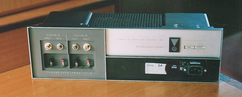
I fitted new RCA inputs and level adjust pots, IEC mains input
socket and fuse holder.
Fig 4.
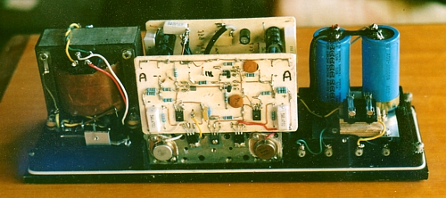
This Fig 9 view is with all the covers off and the amp lying with
the panel face down.
The boards for each channel are white fiberglass with wire tracks
and surface mounted R,C, and other parts.
New PS capacitors are fitted on the right side with a pair of
fuses for the outputs in front of the caps.
Fig 5.
With all covers screwed into place. The amplifier unit fits into a
long speaker unit for an organ with speakers
at each end.
To Re-engineered amps
To Index Page.