Development of 10 Tube Integrated
Preamp. 2006.
Last edited 2015. Content of this page:-
Fig 1. Picture 10 tube preamp in 2,000.
Fig 2. Schematic 10 tube preamp April 2000.
Fig 3. Picture 10 tube preamp. 2004.
Fig 4. Block diagram preamp Sheet 1. 2004.
Fig 5. Schematic Phono amp Sheet 2. 2004.
Fig 6. Schematic basic cascode 2 triodes. 2015.
Fig 7. Schematic basic SRPP and µ-follower. 2015.
Fig 8. Schematic Line level and tone control Sheet 3. 2004.
Fig 9. Schematic Gain pots and output buffers Sheet 4. 2004.
Fig 10. Schematic PSU preamp Sheet 5. 2004.
Fig 1. Prototype 10 tube preamp in 2000.
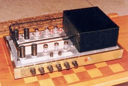
The above preamp picture was taken in 2000. The picture quality
has suffered digital image
degradation over time by unknown behavior by previous ISPs.
There are two rows of 5 twin triodes for each channel. In 1994
the amp had only 6 twin triodes.
By 2000 I had included two pairs of L+R outputs with cathode
follower buffers and tone control,
hence the total of 10 tubes. The preamp chassis sides are formed
from a 1.2 mm sheet brass
channel section 50mm vertical, 25mm legs top and bottom. The 4
pieces of channel have mitred
corner joins with internal angles for strength, and all gaps
less than than 0.5mm gaps, and filled with
solder and sanded smooth to remove any sharp edges. Internal
angles are also held by M4 screws
and nuts.
The chassis top 1.6mm aluminium plate, and PSU is within a 1mm
sheet steel box away from phono
input. Spring loaded tube shrouds are fitted to reduce hum and
electrostatic noise pick up from nearby
sources of stray interference.
Fig 2. Schematic 10 Tube preamp, April 2000.
Fig 2 shows V1a+b 12AX7 in µ-follower mode for MM phono input
stage. It is a surprisingly good performing
amp stage with low output resistance from V1b cathode, with
noise more than 60dB below the 2mVac nominal
"moving magnet" ( MM ) type of cartridge. Some MM carts like
Shure V15 have 5mVac nominal output at 1kHz.
If the MM cart has nominal Vac output of 1mVac, then noise of
the amp is just below the noise of an unmodulated
LP groove.
The passive R&C RIAA filter has R values high enough which
can easily be driven by 12AX7, but low enough to
minimize noise generation.
V2a+b = 12AT7 SRPP, aka shunt regulated push-pull, and is a
second phono gain stage. Total gain of V1 + V2
= 85 x 32 = 2,720, or about +69dB.
The audio signals applied by record cutting head to vinyl LP
have been equalized by a "reverse eq RIAA filter" so
groove amplitude is reduced at bass, and increased above 1kHz.
Please assume the audio signal used to cut records
has a flat response before the cutting head amp and its reverse
eq filter. If a cartridge is used which produces a flat F
response, the output at 20Hz is about -20dB below 1kHz and
output at 20kHz is about +20dB above the 1kHz level.
The rates of attenuation can be seen by Googling reliable curves
for RIAA filtering.
All this means that the output picked up by any cartridge able
to produce a flat response will produce say 0.2mVac
at 20Hz, 2.0mVac at 1kHz, and 20mVav at 20kHz. The maximum
signals produced at V1b cathode are 17mVac at 20Hz,
170mVac at 1kHz, and 1.7Vac at 20kHz, all well below the maximum
Vac possible = 50Vac. Therefore V1a+b THD is
negligible, and well below THD produced by the vinyl cutting
process.
The passive RIAA preamp filter has required 3,180uS and 75uS
time constants both within the one network, plus an
extra HF time constant to attenuate stray signals above 30kHz.
The effect of passive RIAA filter allows 20Hz to pass without
attenuation, 1kHz has -20dB, and 20kHz has -40dB.
Therefore the F response at V2a grid is flat, and 17mVac for all
F. The noise from vinyl is worst at higher F and the eq
process during record cutting and replay greatly lessens the
objectionable noise to levels which have delighted
millions of listeners since the LP was invented in 1949. The eq
process is aided by the fact that audio signal content
above 2kHz reduces in most music, so nothing is ever likely to
be overloaded. V2a+b may produce about 1% THD at
say 10Vrms output, but at 0.54Vac, THD < 0.05%, and mostly
2H, and negligible.
V3a+b = 12AT7 and in SRPP mode for line stage gain. Without the
local shunt NFB, gain is about 32, and this is reduced
by -11dB to 9 by shunt NFB network of R17 47k plus R21 390k.
Therefore 0.54Vac input from phono stage is increased
to 4.86Vac at THD = 0.15%, which seems high, but is not
perceived to be so because THD in tubes is a far smaller
problem than if using discrete solid state devices at these Vac
levels.
S1A+B is a 2 pole 2 position switch to bypass the V3 line stage
amp which would rarely be needed if the signal from
phono stage was high and similar to high standard levels from
many CD players and other Vac sources plugged into
line in terminals 1 to 5 of S3. Line in levels from many older
sources such as FM radios and phono amps was often
only 0.2Vac and these may require use of V3 line stage preamp
and if the power amp needs more than 1.4Vac for
clipping and if speakers have low sensitivity.
V4a+b form a "unity gain tone control amp" with a 12AX7 used
with a Baxandal shunt FB network to allow a fairly
high amount of bass and treble level boost and cut, while 1kHz
levels remain constant regardless of the settings of the
bass and treble adjust pots VR1 500k an VR2 100k, both linear
pots. This type of tone control amp is The Best because
its presence in the signal path is always undetectable by those
with extra special hearing abilities. The THD is extremely
low because the V4a gain without NFB = about 65, but is then
reduced by shunt NFB to less than 1, or by about -36dB,
so that if THD was 2% at 10Vac out without NFB, with NFB the THD
= 0.03%. At 1Vac output THD < 0.003%, and less
than the noise floor.
For purists, I included S2A + S2B to switch the tone control amp
out of the signal path.
Balance control VR3 is a 100k linear pot, and one of 2 within a
dual gang balance pot of 2 x 100k arranged so that turning
VR3 to lower resistance also turns the VR3 in other channel to a
higher resistance.
Volume controls VR4 and VR5 are 100k logarithmic pots, with each
being one pot of a dual gang pot. This allows TWO
sets of Left and Right stereo channels to each be adjusted for
different levels. This allowed me to set up two pairs of power
amps and have speakers able to be switched to either pair of
amps to compare amplifier performance, after pre-setting the
power amp output levels to be equal using a volt meter. Using
this method, I found very few people could tell me which amps
I were powering the speakers when I switched speakers between
the amps, and it confirmed my suspicion that there was
some truth that if good amps measure similarly, and have been
designed and built by the same good bloke, then music is
acceptable and audiophiles often have very ordinary hearing
capabilities.
For most people, there is no need to have dual pair of L+R
outputs.
V5a + V5b are triodes in 12AU7 and in cathode follower mode and
work with a high amount of local series voltage NFB and
the gain of about 12 without NFB is reduced to 0.91 in CF mode.
The Rout < 700r, and THD at 1Vac < 0.03%. The Idc in each
1/2 12AU7 is about 3.8mAdc, and this allows up to 20Vac output
if the output load looking into a power amp or other device
is a low 10k0. A 5 metre interconnect cable using RG58 coax
would give a C load of 335pF and HF pole = 67kHz, so the cable
C will not affect audio signals below 20kHz.
By 2004 I could not resist change to µ-follower gain stages
instead of SRPP. A few people have emailed me to say they built
the 2000 preamp. All were pleased with results. I see no need to
give 2000 PSU details because there is an up-graded
version seen below at "10 Tube Preamp 2004" Sheet 5.
The 2000 amp was reformed again........
Fig 3. Reformed 10 tube pre-amp, 2004.
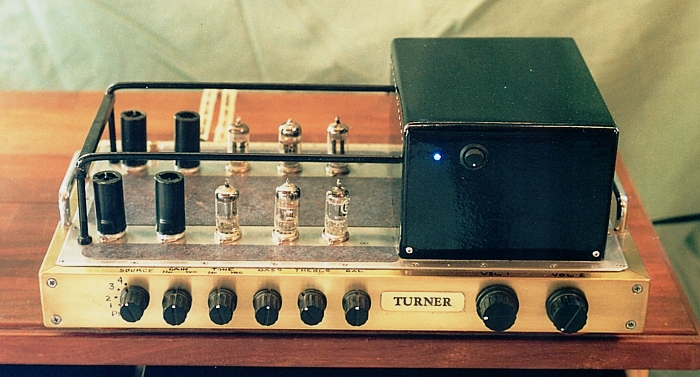
The 2000 10 tube preamp was an excellent performer with a Shure
V15 MM cartridge with high output driving
µ-follower 12AX7. But after I made better loudspeakers I bought
myself a Denon DL-103 moving coil cart to
replace the Shure.
The Denon has less than 1/10 of the Shure output, ( 0.4mV ) and
any 12AX7 then becomes too noisy no
matter how carefully one selects the brand of tube. With MC,
volume must be increased x10 to get the same
preamp Vo. And when volume is turned up, so is the noise, and
this is determined by SNR at the input of the
first phono stage.
In other preamps I found paralleled 6DJ8 were also too noisy
even though calculations and theory predictions
suggested this should not be so. I thought of using 6C45p, but
nobody online has ever given exact performance
details or descriptions, and I decided to try Allen Wright's
basic idea of a cascode phono input stage with a j-fet
input.
The changes between 2000 and 2004 meant moving two switches on
top of chassis to front "panel" and
covering over dis-used holes in chassis top plate with phenolic
kitchen bench-top material well glued.
I kept the PSU box to give good magnetic shielding. There are
two PTs, one for B+ and other for heater Idc
and both are potted to further reduce stray magnetic and
electrostatic fields which can affect sensitive phono
input stages, especially so with j-fets. There was no need to
have a remote chassis for PSU, but don't let me
stop you making your PSU remote.
The schematics of the 10 Tube Preamp 2004 are numbered Sheet 1
to Sheet 5.....
Fig 4. Block diagram of 2004 amp, Sheet 1.
Fig 5. Phono amp, Sheet 2.
Sheets 1 to 5 show the 2004 preamp :-
Sheet 1 = general block diagram for the preamp.
Sheet 2 = Phono input, Q1 2SK369 j-fet driving into cathode of
single ended V1 6EJ7 frame grid pentode wired
as a triode used as "grounded grid triode" in a cascode circuit.
V1 6EJ7 drives a passive RIAA eq filter.
V2a+b = 12AT7 µ-follower second phono gain stage. The output
from V2b cathode is to an input at 2 pole 6
position rotary wafer switch.
Sheet 3, 4 and 5 appear below.
Sheet 2 phono amp.
In 1996 I was very favourably influenced by 'The Preamp
Cookbook' written in 1988 by Allen Wright who had
discovered that vacuum tubes were indeed wonderful for analog
audio signals. Allen departed from this world
in February 2011, but his website is still worth a read for
information about preamps at http://www.vacuumstate.com
Allen's 1988 idea for phono input was to use a high
transconductance j-fet 2SK147 to drive a triode in cascode.
You could get gain up up to 800x at quite low THD and with about
-20dB less noise than when using a well
chosen 12AX7.
Allen's Four Valve Preamp of 1988 was a landmark design where he
combined the best aspects of a j-fet with
tubes. In 1988 Vinyl was still extremely popular despite digital
technology invasions.
The Hitachi 2SK147 with Pdd rating 0.6W is no longer made but
has identical properties to Toshiba 2SK369
except for Pdd of 0.4W. These delicate TO92 package devices are
rated for max Vds = 40Vpk and max Id =
30mApk and for class A idle condition Eds should not exceed
20Vdc, and Idc should not exceed 7mAdc which
gives Pdd = 0.14Watts. The input gate noise is less than 0.1uV,
lower than a good signal triode with 1uV,
if you ever found a good sample. 2SK369 is available from
http://wescomponents.com.au at Ashfield Sydney for
about $1.20 each, and samples I used were remarkably well
matched.
Unlike bjts which have low collector idle currents of say
0.2mAdc for lowest noise, 2SK369 has its low noise at
5mAdc. Gm = 40mA/V, and Rd = 80k, so its signal parameters are
like a pentode with Gm 40mA/V, Ra 80k and
µ = 3,200. To get near these figures using tubes, you would need
about 12 x 6AU6 in parallel, but because of the
low Vd-s rating of 40V max, safe Vo max = about 10Vrms.
Because of high Gm, and high Rd, the 2SK369 is an ideal current
source to drive the cathode of a grounded grid
triode in an input stage. The triode cathode input resistance is
usually its anode load / voltage gain and is usually
less than 1k0. With drain load of 1k0, 2SK369 has open loop gain
of 1,000 x 0.04 = 40, and with phono cartridge
signal of say 0.5mV its drain Vo is 20mV at low THD and very low
noise.
Following the work by j-fet, the triode stages handle higher
signal levels without high THD, all without any GNFB.
Therefore a low noise MC phono amp can be made without using any
loop NFB for RIAA eq or for any other reason.
If you have ever examined the late Allen Wright's website, you
may have come across the "white paper" which
has Allen telling us the secrets about getting good sound from
vinyl. There is a good read at :-
http://www.vacuumstate.com/fileupload/SP_15_Article.pdf This
link still works in 2015.
Cascode is not the same as cascade. Cascade is
where there are two common cathode gain stages with the
second tube grid driven by the anode of first tube. Cascode has
two tubes or other devices in series, and some
basic info about this is here.....
Fig 6. Cascode basics with 2 triodes......
Anyone could build this exact schematic which could be used for
the input stage for Moving Magnet phono cartridge.
The B+ must be rather high at +338Vdc because we have 2 triodes
plus a dc carrying RLa load in series.
If anyone does build this, they must bias the heater Vdc supply
at about +65Vdc so that the max Vdc rating between
heaters and cathodes, ( often 90Vdc ) is not exceeded.
Overall cascode gain is not large at 102. This was calculated
based on the given Gm and Ra for 1/2 a 6DJ8 with the
Iadc = 3.5mA and Ea at +120V. So expect gain in your circuit
between 90 and 110, and variation is because Gm
and Ra vary slightly for sample tube.
Output Rout from V1b anode is determined mostly by RLa load
17k5, because the V1b Ra becomes effectively high,
about 175k, because its Rk is the Ra of V1a.
V1b acts like a current source of 175k working on all DC and
C&R coupled loads in parallel. Cascode gain is roughly
proportional to the total RLa load values.
Effective V1b Ra' may be calculated :-
Ra' = Ra + ( [ µ + 1 ] x Rk ), where Ra is for V1b and Rk
= Ra of bottom tube.
So in this case, Ra' = 5k0 + ( [ 33 + 1 ] x 5k0 ) = 175k. If V1a
had its Rk of 1k0 unbypassed, then V1 Ra' effective
= Ra + ( [ µ+1 ] x Rk ) = 5k0 + 33 x 5k = 39k and the Ra' for
V1b will increase to 1,331k, or 1.33Meg, and gain of V1b
becomes closely proportional when V1a total RLa is only 50k.
Rout from cascode = Ra' // RLdc, in this case 175k // 27k =
23k4.If V1a Rk was unbypassed, Rout at V1b anode
= 1,331k // 27k = 26.4k.
My triode cascode circuit shows cap coupled R4 50k. This R value
is typical of a the Rin to an RIAA network 1kHz.
Passive RIAA networks have varying input Z, with higher Z at
20Hz and slightly low Z at 10kHz. If the cascode stage
shown does drive a passive RIAA network then R+C values chosen
for the network must include for effective Rout
of the stage, in this case about 23k4.
Most inexperienced ppl get this part of circuit design
hopelessly wrong!
The SNR in triode phono circuits is mainly determined by the
unavoidable grid input noise and shot noise which is
rarely less than 1uV in good samples of most small signal
triodes such as 1/2 12AX7 or 6DJ8. If an MM cart has
Vo = 4mV, then SNR = 1uV / 4mV = 0.001 / 4 = 0.00025 = -72dB.
Much of the triode noise spectrum will be below 1kHz.
Noise in other parts of a possible preamp may reduce this SNR by
+6dB to - 66dB. The noise of the triodes is just below
noise of an unmodulated vinyl groove so that when amp gain is
turned up with cart in a quiet groove you hear the vacant
groove, and with very little amp noise able to be heard. With
the MM cart, the gain will rarely ever need to be turned up
high enough to hear the vacant groove noise, hence vinyl is an
acceptable true hi-fi source providing the grooves are
clean and free of muck which produces crackles & pops. The
vacant groove noise probably has some noise from the
tape source used when cutting the record. A quiet recording
venue or hall where there is total audience silence may
still have noise.
Grid input noise is theoretically inversely proportional to
square root of Gm. The higher the Gm, the lower the noise.
So if 2 x 1/2 6DJ8 are paralleled, noise reduces x 0.707 ( in
theory ).
The 6DJ8 has much higher Gm than 12AX7, yet in practice noise is
often no lower than many 12AX7.
With 2SK369 j-fet, the gate input noise is commonly below 0.1uV,
and the vacant vinyl groove noise dominates,
even when gain is turned up.
I've never known a phono amp with tube input to give acceptably
low noise with any MC cart. For silent periods
during classical work you don't want to hear sausages on a
barbecue in the background. Phono input tubes age
like all others and their noise can increase 4 times in 4 years
of constant use. Gas entry over time is the main cause.
Cascode circuits with 6DJ8, 12AT7, 6AQ8, 6BQ7 were very useful
in RF circuits for TV and FM tuners.
The medium low input noise of these triodes exists in both
cascode and cascade triode stages. Usually the triode
noise is noticeably lower than in a pentode because of the
"partition noise" relating to the g2 screen.
This disappears if the pentode is triode strapped. Almost
anything is better than an EF86 used in a phono stage
as it was done in 101 preamps of the 1950s.
Following the first use of vinyl for 33.33RPM records in 1948,
and 45RPM in 1949, Denon invented the famous
DL-103 Moving Coil magnetic cartridge in 1962. It is still being
made, and I have a DL-103 rated for 0.37mV
output which I have used since 2004. I found it took only 5
minutes use to discover it made better music than a
Shure V15. In the 1960s a good SNR with MC needed a step up
transformer to increase the 0.4mV to say 4mV,
ie, 1:10 step up.
Data for Denon MC, DL-103R :-
Stylus: 16.5µm diamond spherical tip.
Cantilever: Aluminium.Frequency Response: 20 ~ 45kHz.
Output: 0.3mV at 50mm/s.
Output Impedance: 40Ω.
Load Impedance: 100Ω.
Channel Separation: Over 25dB at 1kHz.
Compliance: 5 x 10⁻⁶cm/dyne (100Hz).
Tracking Force: 2.3 ~ 2.7g (± 0.3g).
Weight: 8.5grams.
If the Denon has 100r load and no trans, the total R = 28r, and
noise will be much less than any triode input noise.
The j-fet with high Gm and very low noise avoids ever needing a
step up transformer.
Typical gate input noise of 2SK369 is mainly HF hiss with much
less rumble and LF sputter you get with tubes.
So with RIAA filter reducing all input signals by roughly
6dB/octave above 50Hz, the majority of j-fet noise is reduced
and output amp noise is MUCH lower than any tube could provide.
High Gm j-fets such as 2SK369 are nearly always used with drain
load R much less than the internal dynamic Rd
of say 80k. J-fet loading is similar to loading pentodes where a
load for EF86 might be 150k, while its Ra = 1M0 or
more. Because j-fets are "transconductance devices" with gates
drawing no current and drain current altered by a
change of gate voltage, the parameters for a j-fet could be
specified similarly to tubes in terms of µ, Gm and Rd.
While this is convenient for triodes, j-fet Rd is affected by
capacitances and Rd is really only the value we find at
low F where XC is many more ohms than Rd. In tubes, the
amplification factor µ = Gm x Ra, and in 2SK369,
if Gm = 40mA/V, and Rd = 80k, then µ = 0.04 x 80,000 = 3,200.
Gain for tubes = µ x RL / ( RL+Ra ), or, if we
neglect µ, gain = Gm x ( RL // Ra ). If Ra is many times RL then
it may be neglected.
The effective Rd' of the j-fet is increased if there is an
unbypassed Rs. If Rs = 50r, then Rd' = 80k + 3,200 x 0.05k
= 240k, very hi Z. In a cascode circuit driving a triode, the
high Rk is many times higher than the triode RLa, so any
THD produced by triode is much reduced by the local current FB.
The THD of the cascode stage is mainly produced
by the input device. This THD is mainly 2H which is highest when
drain load < Ed / Id. If 2SK369 has Ed = +12Vdc
and Idc = 5mA, Ed / Id = 2k4. The open loop gain is 96.
If the drain load is increased I found 2H declines to a null
with RLd = 6k3, and then increases with some 3H as RLd
increases. Typical THD with RLd = 2k4 increases at a rate of 1%
per 0.4mA Ia so at 7Vrms with 2k4 you may get
THD = 7%. This is far higher than what you get with a pentode at
Vo 7Vrms with typical load of 100k.
But if gate Vin = 0.2mV, load current change = 0.0002V x 40mA/V
= 8mA, so expect 2H = 1% x 0.008 / 0.4 = 0.02%,
and if there is 10dB of current FB with an unbypassed Rs then
THD < 0.008%.
Let us not worry about such tiny things.
--------------------------------------------------------------------------------------------------------------
Calculations for 2SK369 driving the triode strapped 6EJ7 in
Sheet 2 :-
The 6EJ7 triode data for Ea = +130V, Ia = 5.4mAdc give Ra =
10k6,
Gm = 5.2mA/V, µ = 55.
The RLa total at 1kHz = 15.66k.
6EJ7 triode gain A = µ + 1 / ( [ Ra / RL ] + 1 ) = 56 / (
[ 10.6 / 15.66 ] + 1 ) = 33.4.
Suppose Va = 57mVac. Then Vk input = 57mV/33.4 = 1.7mVac. The
signal load current Id = Ik = Va / RLa
= 0.057V / 15.66k = 0.00364mA. Therefore cathode input R = Vk /
Ik = 0.0017V / 0.00364mA = 467r.
The cathode Rin = drain load for 2SK369. Assume link 1 Sheet 2
is used as shown.
This gives Rs = 50r. The total loading for 2SK369 = 469r + 50r =
519r.
The j-fet gain = Gm x RL = 0.04 x 519r = 20.76. Iac in triode
and j-fet = 0.00364mA.
Vac across Rs 50r = 50r x 0.00364mA = 0.182 mV. Total Vds = Vd +
Vs = 1.7mV+ 0.182mV = 1.882mV.
Vgs = Vds / Gain = 1.882mV / 20.76 = 0.091mV. Therefore, to make
57mV at V1 anode, we need Vgs
= 0.091mV so the j-fet open loop gain = 57mV / 0.091mV = 626.
We have 0.182Vac across 50r, so Vg-0V gate input = 0.182 + 0.091
= 0.273mV.
The 50r gives 10dB local current FB and final overall gain =
57mV / 0.273mV = 209.
Gain reduction factor = closed loop A / open loop A = 209
/ 626 = 0.33 which is about -10dB NFB.
To verify these calculations by measurement of Sheet 2 depends
on accurate measurements of tiny Vac
prone to noise and high inaccuracy. But you can what you can
expect. If you build two channels, and
the same input signal is moved from one channel to the other,
and you have equal Vout from each triode,
then you have two good channels, and I have found that a couple
of randomly chosen 2SK369 j-fets from
a batch of 10 purchased will often give channels matched within
+/- 0.5dB, quite closely.
>The 6EJ7 could easily produce Va = 5.7Vac at low THD. With
all Vac 100 times higher than might appear
in normal working, there is a better chance of measuring Vac
input and gain accurately.
Now there's a quicker way through this mass of figures. In
cascode circuits where bottom device is a
current generator controlled by input voltage and its Ra or Rd
is well above 100 times its RL, the overall
gain may be more easily calculated :-
Gain A = RLa of top triode x Gm of bottom device. How
simple!
We have RLa = 15.66k, and j-fet Gm = 40mA/V, so gain = 15,660 x
0.04 = 626.
This is the same as all those figures above calculated. If you
use other tubes for V1, 6BX6 or 6AU6 in
triode, or paralleled twin triodes like 6DJ8, 12AU7, 12AT7, the
gain remains almost identical.
12AX7 or 12AY7 would be unsuitable because when paralleled they
still could not have idle Idc = 5mA
without operating in grid current regions to give high THD.
The 1kHz output after RIAA filter is 6.6mV. This filter should
reduce the 1kHz signal -20dB ( x 1/10 )
below levels of very low F at say 5Hz. In other words, V1 Va
should be 66mV at 5Hz. but you cannot ever
measure 66mV because of gain variation with high Rout. To avoid
more incomprehensible ideas about
the stage gain, just use a reverse RIAA input filter and adjust
R RIAA network values until you get a flat
sine wave response between say 20Hz and 20kHz, -3dB poles. The
1kHz square wave should look very
square with no curvature in horizontal parts of square wave.
There are LF poles in Sheet 2 with C2 9uF+47k 0.37Hz, C10
0.47uF+470k 0.72Hz, C13+1M 0.34Hz,
C14 0.47uF+1M 0.34Hz. All these poles give theoretical LF
cut off of -3dB at about 2Hz. Above 2Hz,
the sine wave response at Vo should rise to a flat line until
about 10kHz when a slow roll off rate begins.
The amp gave me the flattest sine wave response using R&C
values as shown. The trimming R in RIAA
filter have been optimized to include possible capacitor values
being 5% incorrect. Most better C brands
made after 1990 have C within +/- 2%, and R values of 1% are
often better than 1%.
-----------------------------------------------------------------------------------------------------------------
Fig 7. Basics about SRPP compared to µ-follower.
Fig 7 shows SRPP and µ-follower gain stages using 12AT7.
The SRPP is similar to V2, in Fig 2, ( 2000 preamp ) above.
The µ-follower is similar to V2, in Fig 5, Sheet 2, 2004, ( 2004
preamp ) above.
So how do the two stages compare? which one is better?
The 2000 SRPP has highest Rout and THD and slightly lower gain.
We may conclude that where the RL > 2 Ra then the µ-follower
will always has lowest Rout and THD,
and highest gain.
For the SRPP, if R3 is unbypassed, the 1k5 gives considerable
local current FB and I predict gain = 17.
But the LCFB will reduced THD by -6dB.
The µ-follower can have its R8 bypassed for much lower Rout than
SRPP. Because the anode load of
V3a is also higher than for V2a, V3a has low THD.
Below, in Fig 8 there are two more µ-follower stages used for
optional gain and tone control stages.
These show some variation but you may conclude the µ-follower is
better than SRPP.
Both SRPP AND µ-follower are better than having normal common
cathode gain stage followed by a
direct coupled cathode follower, for application where the
stages power the known internal amp loadings.
With the series connected triodes there is a large saving in
anode power to the 2 triodes because there is
no DC power lost in an anode to B+ resistance or cathode to 0V
resistance for cathode follower.
With so many triodes, it all adds up. With series triodes, each
triode gives an active load to the other.
I could not find or work out a single accurate formula for
calculation of overall gain for µ-follower stage
with 2 identical triodes in series. So just how it works needs
several calculations, and comparison to SRPP.
SRPP operation exists where the two series triodes have equal
Rk. Where you have Rk of top triode
= 5 x Rk+ of bottom then you have drifted to µ-follower.
There are many variations of µ-follower which you are free to
explore, but I found what I used in 2004 to
sound just beautiful, and the two triodes in the one tube can be
easily wired for each stage in each channel.
--------------------------------------------------------------------------------------------------------
About Phono amp input, Fig 5, Sheet 2.
In Sheet 2, I have C2 6.8uF NP // C3 2uF polypropylene 2uF to
couple the output of any MC or MM cart
to very high impedance of gate input of Q1 2SK369.
Q1 gate is biased to +1.4Vdc via R1 47k. Q1 source has Es =
+1.47Vdc approx.
R2 50r and R3 220r form Rs = 270r which sets the idle Idc in
V1+Q1 = 5.4mAdc.
Some question the high value 8.8uF gate coupling cap value but
we must remember that the LF noise
in a 47k bias resistor is considerable, so it must be shunted by
low reactance to the low Z cartridge.
The LF pole between 8u8 and 47k is 0.38Hz, so noise above this F
is well reduced by choice of high C
value. Any LF noise below 20Hz is amplified by the full open
loop gain of the amp because there is little
attenuation of such low F by RIAA filter. People may dislike C
used for coupling here, but in general C
coupling is unavoidable and essential in all good audio
amps, along with C bypassing of cathode circuits
and in PSU.
Phono stage gain is varied in 3 ways by moving a soldered link
which moves C5+C6 470uF to 3 positions
to vary gain by changing the amount of local current source FB
for Q1. For carts with the lowest signals, there
is full bypassing of R2+R3, for medium V carts R3 is bypassed,
and for high Vo carts there is no bypassing.
The selectable gain will allow use of a wide variety of
cartridges. Where there is no provision for variable
input V of carts it is very likely there will be problems with
use of a sensitive line preamp and power amp
and speakers where the slightest movement of a volume control
has the system trying to deafen the listener.
I use large electrolytic filter cap ( C4 = 470uF + C16 2uF ) for
phono amp B+ to stabilize the rail to help
prevent LF or HF noise in B+ rail being amplified by the high
amp gain at LF.
I circuit as shown tended to oscillate at about 100MHz if the
circuit board area for the j-fet plus V1 was
larger than 50mm x 50mm in total area, and if leads to
capacitors and track lengths were too long, and
even with good "star" earthing. Phono stages with high Gm
devices must be treated like RF circuits,
and "small is beautiful" in this case, and expect to have to at
least have all electro-C bypassed with plastic
caps and perhaps use ceramic 0.1uF plus have leads all shorter
than 30mm.
Bypass capacitors C1, C5,6,7,8,9 are very important. I also
supplied the DC to the heaters to V1 via RF
chokes and bypassed the heater wiring well with C to prevent
parasitic oscillations. The RF chokes are
0.8mm enamel wire wound as solenoids of one layer along a 30mm
length of 10mm ferrite rod.
Tubes such as high transconductance frame grid pentodes like the
6EJ7 make fabulous triodes for my
purpose, but whatever you do, don't try to use them as pentodes
driven by a j-fet as shown.
The extremely high resultant gain WILL be impossibly unstable at
some high RF and the tube will be
weirdly microphonic, and you'd think you had the bells of St
Mary's Cathedral connected to your amp.
In 2005, I developed a superior cascode MC amp circuit which is
described in the page
for Rocket phono amp.
Fig 8. Integrated line level and tone control, Sheet 3.
Fig 8, Sheet 3 shows V3a+b is 12AU7 µ-follower line level gain
stage which can be switched in or out of circuit.
This allows input signal from line inputs or phono amp to
connect directly to the gain control pots or have signal
increased +15dB or +10dB approx. I found it useful with low
sensitivity power amps and speakers, or where line
levels was high ( from CD player ) or low, ( from old AM/FM
tuner etc ).
V4a&b is 12AU7 µ follower tone control stage with Baxandal
feedback circuit and able to be switched in or out of
circuit. Gain = approx 0.94 with +/- 9 dB of max cut and boost
at 100Hz and 10 kHz. This stage is seldom used
except when testing speakers and sources to gain a very
approximate idea of response problems. Some vinyl
or AM/FM radio sources can benefit with tone controls.
Balance is controlled by pots prior to the line level gain
stage. I saw little reason to ever use balance controls and
when the line gain stage is switched out there is no balance
control. All CD I have heard have acceptable balance.
The volume is controlled by pots placed immediately before 12AU7
cathode follower output buffers which use
cathode current sinks with bjts, to enable optimal Idc in
triodes for high Vo and low THD.
Most of the time the line stage and tone controls are not used.
So line input from RCA input terminals may be
applied directly to the gain control pots ahead of 12AU7 output
buffers to reduce the number of am stages to an
absolute minimum. The cathode followers convert the highish Rout
from volume pots to low Rout < 600r which
allows long interconnect cables of say 5 meters with C of 600pF
without audio F losses.
Fig 9. Gain pots, Output, buffers, Sheet 4.
Fig 9 Sheet 4 shows 1 channel and how I have dual volume control
pots VR4 and VR5 so I can use 2 pairs of L+R
cathode followers for 2 pairs of L+R outputs to facilitate A-B
testing of other equipment. Unless careful AB testing
is done, how does anyone know if any difference exists between
power amps or speakers? I can have the same
input source but preamp feeds 2 pairs of L+R power amps, each
level adjusted so that when speakers are switched
from one power amp to other there is no perceivable level
change. The only thing which may change, and possibly
be noticed by a listener is the sound quality. It is remarkable
how often nobody can hear any change to sound of
power amps.
The cathode followers have transistor CCS between cathode and 0V
for a high Z Idc sink, aka CCS. This reduces
loading by by resistors carrying DC, and to maximize open loop
gain of the 12AU7, and hence minimize the THD,
and allow the load powered by the cathode follower to be a lower
ohm value than would otherwise be tolerated.
The only "sonic signature" of such a CCS is to improve the sound
quality.
Fig 10. Power Supply, Sheet 5.
The 2004 PSU is more sensible than the original 1994 amp which
had two PSUs including two PTs for B+ for two
completely mono channels.
I found there was no need for such complexity on a single
chassis and one B+ rail and one Vdc heater supply works
perfectly. There is one B+ choke included in a passive CLCRCRC
filter for the B+. There is no need for B+ regulation
except for the phono amp B+ rail. Heaters are all DC and
regulated.
The anode current consumed by each channel = 20mA approximately,
so with a total of about 44mAdc and B+
across C4 = 290Vdc, the B+ power consumed is about 12W.
I have used the available 240-0-240 CT winding for full wave
rectifiers with 2 Si diodes. The actual VA rating for the HT
winding should be 30VA. It allows for overload or something
shorting and a lowish value input mains fuse.
To get about +285Vdc (working) and say +320Vdc unloaded, HT Vac
could be 120Vac (unloaded) used for a doubler
rectifier OR a 240Vac for a Si bridge. It is easy to have B+
which is too low, and it cannot be raised, but if B+ is a bit
too
high it can be reduced by some extra series R between Si diodes
and caps or further along the RCRC filtering.
I did not see a need for B+ regulation, although fanatics would
have B+ regulators for every stage of each channel.
Feel free to design your own method of B+ regulation. The
regulation is always something else which can go wrong,
so I try to avoid it. But when it is done right the regulators
prevent LF noise in B+ rail generated by the constant mains
voltage level change because of people sharing the Mains supply
line and switching heaters, stoves, electric jugs, air
cons et all. Such noise can get to the signal path if the B+ is
not very well filtered. I found the use of CLCRCRC was
sufficient to keep very low F out of the amp output when using
phono source where there is highest likelihood of seeing
very LF noise at amp Vo because the LF gain is very high with
RIAA filter. This amp has low enough LF noise, helped
by RC coupling between stages.
In a later phono stage, the Rocket, I did
use regulation for the B+ applied to phono stage. The Rocket is
a stand
alone unit needing a remote PSU and the regulation guards
against use of an inferior quality PSU made by someone else.
This amount of B+ power is similar to that required by an old AM
radio. A PT found in many old AM radios will provide
the B+ power needed by this preamplifier. But it is always
better to begin with NEW PTs. I am sure Hammond make
something suitable for B+. If a chosen PT does not have
heater windings capable of 23Watts to heat 10 preamp
tubes a second PT must be used.
I found a suitable heater PT, 60VA from Jaycar, an Australian
parts supplier. It has several taps and allows up to
2A at 30Vrms output. Most of the power drawn by the preamp is
filament heater power.
The preamp has the power supply within a steel box with steel
bottom and removable top. The HT PT is NOS potted
ex-Navy, and the heater PT is potted in a steel can filled with
dry sand to keep it mechanically quiet and reduce stray
magnetic fields. The combined effect potting and mild steel
sheet box reduces stray magnetic fields just enough to
allow the very magnetically sensitive phono input circuitry to
be placed only 450mm away from the power supply
on the same chassis.
It is always better to use a remote power supply and umbilical
cable, but the TWO layers of magnetic shielding were
enough to exclude effects on the phono stage which has a very
magnetically sensitive j-fet in input stage.
I used brass and aluminium for the main parts of the chassis
which looks nice, but plain 1.2mm mild steel is better
especially if other devices such as CD players in plastic cases
are located near the phono amp. Keep power amps
away from phono inputs.
The heater Vdc is regulated by circuit around Zd1, Zd2, Q4, Q5.
The whole heater supply is biased at about
+56Vdc so that the dc voltage difference between heaters and
cathodes does not exceed the ratings of 90Vdc
so arcing or current leakage from cathode to heater circuits is
prevented. Such leakage is rare in new tubes,
but never fully preventable regardless of Vdc between cathodes
and heaters. Old tubes in amplifiers can have
slight cathode-heater leakage which causes slowly increasing hum
to develop where the heaters have AC
heating current. I have seen old tubes get rare shorting between
heaters and cathode; it is easily fixed,
- just replace the tube.
To achieve good ripple rejection in the 1.8 amp dc heater
supply, the easiest way is to use a regulator rather than
have an ungainly large choke and huge capacitors. But please
feel free though to use as much L and C and or R
as you can afford..... The overall pre-amp performance...
Bandwidth is 3Hz to 100kHz, -3dB.
Rout < 600r, able to drive any known tube, solid state power
amp, sound card.
Connections. I have plenty of RCA inputs, record output, and
dual L+R outputs.
THD < 0.02% at 1Vrms output.
Wiring style is mix of point-point with tag strips plus a
fibreglass board with copper wire tracks and some surface
mounting of R&C parts.
I used mainly Wima polypropylene capacitors for the signal path
couplings and 1% x 1W Welwyn metal film resistors
or good quality 1W rated metal film R from reputable makers in
Taiwan.
I never believed in many myths about special parts. The circuit
topology, design, tube choice are far more important
to the sonic signature than brand of capacitor. I have heard
claims by DIYers for how capacitors "sound" and then
found the overall quality of their system was un-listenable
because they didn't believe any measurements were
needed and they could just rely on their ears.
Back to Preamps directory
Back to Index Page