THE
ROCKET PHONO AMP, Dec 2005.
Edited 2018.
The Rocket still goes on rocking!
Contents :-
Picture of a very good system,
Picture of the Rocket.
Schematic Sheet A and B of the Rocket, Full schematic explanation.
Basic cascode explained with 2SK369 and 6DJ8.
Schematic of reverse RIAA Eq testing circuit.
Picture of chassis underside of Rocket with Wimas and Auricaps
For Rocket power supply, see the PSU details at preamp-nemo-line-psu-2005.htm
One of my customers once asked me if he could get better music
with a tubed preamp as an alternative
to his USA made Sutherland phono amp which had all solid state
op-amps and was battery powered,
and which cost $3,300 in about 2004.
I thought I could do better with tubes, but I would have
to use just the ONE solid state device in the
signal path, a single 2SK369 j-fet as the phono input device.
My customer had enough quality elsewhere in his system to allow
the benefits of a better phono amp to
be heard.
He had a nicely sized room, well carpeted and furnished to
reduce reverb and glare from too much treble.
His speakers in 2005 were Vienna Acoustic Mozart, with Townsend
super tweeters, and a custom
built subwoofer which I built. Sub amp is Musical Fidelity A3CR.
The power amps are 22W monobloc SEUL 13E1 that I built in 1997,
upgraded for 2003, and the
preamp at line
stage preamp is also one of mine.
The line stage was upgraded in 2005, and its power supply
re-built to power both Nemo line preamp
and the Rocket phono amp.
His vinyl replay uses a Michel Orb TT with an extensive sand and
wire damping kit from a dude in
Denmark, the cartridge was Helicon Lyra.
Cabling is thin wire home brew plaited for interconnects.
Speaker cables are Nordost. All up, this
system is one of the few I am very happy to spend hours in front
of, and despite my client's pair of
good quality silver disc players for CD, SACD, DVD, even
including a Sony player with Allen Wright's
special upgrade.
We both find that vinyl sounds better, and is more emotionally
engaging, unless the recording isn't good.
It is remarkable how often they got it right in the studio or
venue in the analog 1970s, and they cannot
do much better now when surrounded by digital gadgets, and even
with 96/24bits, and now, hard drives
and goodness knows what.
Gary's system was extremely listenable.....
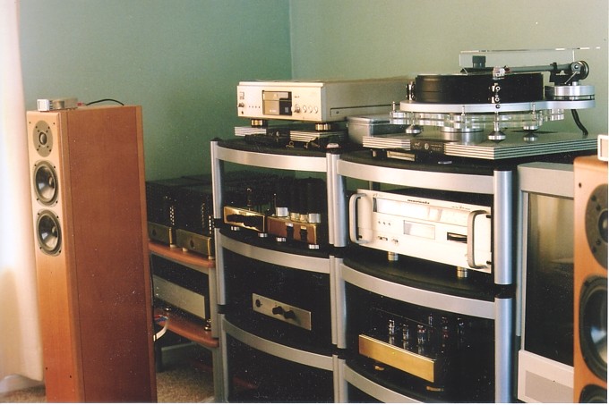
Directly below the Michel TT is a Marantz tuner, then the
"Rocket" phono amp I built.
The line stage preamp and power supply for both line and phono
stages are to the left
of the silver colored Marantz tuner.
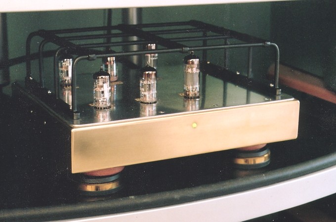
The "Rocket" six tube phono amp, Dec 2005. It rocks! But sounds
just right for classical
Sheet A amp schematic, 2005, edited 2011.
General features :-
The phono amp has j-fet + triode cascode input stage followed by
triode µ-follower output stage.
Passive RIAA eq filter in one network is used between the two
gain stages.
This circuit gives low noise and distortion, wide bandwidth,
enormous headroom.
The output µ-follower stage gives Rout < 1k0 and will drive
any tubed or solid state preamp or
sound card for recording vinyl onto a CD.
The circuit can be matched to suit the type of phono cart used,
MM or MC.
For MM :-
The link "MC link" is not used.
R1 is not needed, so nothing is connected where R1 is shown. C3
may need adjustment to comply
with cartridge specifications and turn table C. Without the
link, gain at 1kHz = 45dB, and will suit
all MM carts including those with rated 1kHz Vo < 1.5mV,
giving amp Vo at 1kHz < 270mV.
For MC :-
The "MC link" is used.
R1 should be used if MC cartridge manufacturer recommends it.
Usual values of R1 can be from 100r to 1k0. MC carts have source
R < 50r, and their output level
is not much altered by R1. With MC link amp gain is up to +57dB
at 1kHz, so an MC cart rated
for a low 0.2mV at 1kHz will give 140mV at amp Vo.
I have used a Denon DL-103 MC with rated Vo = 0.4mV and I get
280mV at amp Vo.
The noise produced by the j-fet input is at least -20dB below
what one gets with a well selected 12AX7
or 6DJ8 etc. Hence there is no need for a step up transformer
for MC use. The j-fet noise is a soft hiss
with mainly HF content which is much reduced by the RIAA filter.
Tube noise has much more LF content
which is not filtered as much by RIAA filter.
Technical details for those with technical education and
experience :-
The cascode input.
The input 2SK369 j-fet has an unusual R network with
R3,4,5,6,7,8,9,10,11 arranged between j-fet source
and shunt regulated -6.2Vdc rail, and all smoothed with C1,2,11.
The 6.2V zener diode noise is suppressed
well enough by the RC filtering. The R network allows for a
minimum effect of electrolytic bypass caps in
the j-fet input circuit, and the gate of the j-fet is biased at
0V so no high value input C are needed between
input and gate. The R network stabilizes Idc flow through V1
triode and j-fet. There is an earlier page
about evolution of the cascode input stage
at 10 Tube
Preamp.
There is much at the earlier page about basic cascode principles
and use of 2SK369.
The schematic above for Rocket input stage is set up so
operation is for high gain to suit MC with link
soldered in. The j-fet source resistance comprises the resulting
total R formed by R3, 4, 5, 6 , 7 and 8 which
is 43.6 ohms.
If the link is removed, Rs becomes higher to increase local
current FB which reduces gain becomes lower to
suit MM cart.
The load seen by the V1 tube varies from a maximum of 23.5k
(ohms) at very low F to about 15k at 1kHz
due to the nature of the impedance of the RIAA filter which
varies with F.
The second phono amp gain stage is µ-follower. Its basic
function compared to SRPP is more fully described
at 10 Tube
Preamp. In this amp I have used paralleled 6CG7
upper triode and 12AT7 lower triode which
are happy with their equal Idc and the result combine the high
gain of 12AT7 with ideal Rout character of 6CG7.
Sheet B regulator schematic, 2005, edited 2011.
The phono amp power supply is from a separate chassis which
provides power to two chassis,
one for line level gain and other for Phono amp.
Cascode explained.
Here is some detail for those able to understand more than
basics
of cascode operation.
This phono input amp schematic includes all necessary
calculations.
In this case V1 paralleled 6DJ8 has its two triodes paralleled.
Each triode has 2.6mAdc giving Ra = 5k0,
µ = 33 and gm 6.6mA/V. For the paralleled 6DJ8, it acts like a
single triode with µ = 33, Ra = 2k5
Gm = 13.2mA/V.
( Ra and Gm vary considerably with the anode current and µ = Gm
x Ra, and µ is the least variable
parameter; please examine the Ra data curves for 6DJ8 or 6922. )
The 6DJ8 is working in common grid aka grounded grid mode and
gain formula is slightly different to
common cathode. The common grid gives gives slightly higher gain
than common cathode mode.
The 6DJ8 cathode Rin is low and = RLa / A = 15k0 / 29.14 = 515r.
Unlike a gate input with
Rin = megohms, the cathode input current = anode signal current.
The 2SK369 drain loading at 6DJ8
cathode = 515r. The 2SK369 Rs = 44r, so total load of 2SK369 =
515r + 44r = 559r. For 2SK369,
internal Rd = 80k and is so much more than RLd it may be
neglected for gain calcs so gain 2SK369
= Gm x total fet RL = 0.04 x 559 = 22.36. The Rs is unbypassed
so it gives local current FB.
The j-fet gain with LCFB = A' = / ( 1+ [ A x (Rs / [Rs + Rd] ) =
8.1014.
Thus fet gain is reduced by factor A' / A = 8.10 / 22.36 = 0.36
= -10dB.
Vg-0V gate input with LCFB = Vds / A' = 0.559V / 8.1 = 0.069V.
The -10dB A reduction reduces j-fet THD by factor 0.36. THD in
6DJ8 is very much reduced because
j-fet Rd acts as very high cathode Rk = Rd + ( Gm x Rd x Rs ) =
80,000 + ( 0.04 x 80,000 x 44r ) = 220k.
Thus the 6DJ8 produces little THD, and j-fet produces most of
the measured THD.
The cascode stage is very effective where we wish to avoid the
anode to grid Miller C. With statically
measured C, 2SK369 data says gate input Cgs = 75pF and reverse
transfer C ie, Cgd = 15pF. Without
LCFB the Rocket j-fet gain Vg-d = 0.515 / 0.025 = 20.6 so Cin at
gate = Cgs + A x Cgd = 75pF + 309pF
= 384pF. This is much to high for MM, and minimum Rs = 44r is
used which suits nearly all MC carts or low
Vo MM.
With LCFB gain Vg-d = 7.3 so Cgd becomes 7.3 x 15pF = 110pF and
Cgs becomes lower
= static Cgs x Vgs / Vin = 75pF x 0.025 / 0.069 = 27pF so total
Cin at gate = 27pF + 110pF = 137pF.
This input C has negligible effect on HF bandwidth where MC cart
Zin < 50r. But MM carts mostly have
unknown Zout and must rely on a cart maker's specified Cin for a
flat HF response.
If a 2SK369 is used for a simple SE common source gain stage
with with RLd = 3k0, then A = 120, and
without local current FB the Cin = 1,875pF which has
unforgivable effects on audio HF response.
There is a huge amount of non precise info on cartridge
properties including their loading. But a good start
to your study may be at
http://sound.westhost.com/articles/cartridge-loading.html
Fig 3 at this page deals with measuring a typical sample MM
cartridge Z out. I calculated 1.88k at 1kHz,
and the use of 47k standard loading R for MM will not cause much
reduction of cart output at 1kHz.
I recall measuring MM cart Vo drop at 1kHz when 47k was
connected and concluded cart output Z was
between 2k0 and 5k0.
The Input C for most MM carts is specified by the maker and is
between 50pF at 500pF, with many at
100pF to 220pF which includes turntable cable C + amp input C.
The total shunt C across MM input has large effects on HF
response above 8kHz.
Too much C will cause a resonant peak in MM response and in
theory, if I have a 1.5M input cable with
C = 100pF, then the input C in Rocket circuit will total about
237pF which suits a Shure V15, but not suit
other carts, where less C is desirable, so it is better to try
to use the lowest C cables you can find, and trim
C3 at Sheet A Rocket schematic above.
To best suit MM use with the Rocket, the MC link is disconnected
at one end and
this much increases Rs, and reduces gain and reduces Cin to
allow higher C in
turntable cabling.
The Rocket has only two gain settings for gain which I think is
enough variation.
Most who want real hi-fi with a Rocket will only use MC.
Data curves for 2SK369
The Rd curves for 2SK369 show useful regions for fairly linear
Id vs Vgs when the idle Q point is Vds
= +10Vdc, Id = 5.2mAdc.
For RLd = 530r, equal +/- 0.1V Vgs change gives Id swing =
+4.1mA, - 3.1mA.
Total Id change = 9.3 - 2.1 = 7.2mA pk-pk = 2.5mArms.
The 2H % = 100% x 0.5 x ( difference Id change / sum of Id
change )
= 100% x 0.5 ( [4.1 - 3.1] / [4.1 + 3.1] ) = 13.89%.
This seems a lot but the 2H% reduces in proportion to Id change
and if Vo = 0.72mA pk-pk change 2H
< 1.39%. In the Rocket, if 2SK369 gain with LCFB = 8.1, and
at 2.5mArms with 559r load the THD is
reduced x0.36 from 13.9% to 5%. If Vg-0V gate input = 0.5mVrms,
Vds = 4.05mVrms and with RL
= 559r the Id = 0.0072mArms so expect THD < 0.0072 / 2.5 x 5%
= 0.014%, low enough to never have
to worry about it.
When the amp is used for MM cartridges with a typical rated
output of 5mVrms at 1kHz and without the
gain link, Rs value is 259 ohms, the amount of current LCFB is
much increased, and gain & THD is reduced.
NOISE.
The "equivalent input noise resistance", EINR, of a j-fet
approximately = 0.7 / gm, where 0.7 is a constant
given in reputable literature such as the British radio amateur
handbooks. Gm is in Amps per Volt.
So EINR for 2SK369 = 0.7 / 0.04 = 17.5 ohms.
The EINR is considered Equivalent Input Noise Resistance which
is an R in series with input to a perfect
noiseless amplifier. Noise is difficult to measure inside the
device and is usually measured at the output, then
input noise = output noise / gain.
Input noise is mainly Johnson noise in EINR, and other noise
adds to total at output such as shot noise in triodes
and partition noise in pentodes. The noise varies in proportion
to the square root of the EINR, so that if the EINR
is increased 4 times, then noise doubles. Or, EINR must be
reduced by 1/4 to halve the noise.
A triode EINR = 2.5 / gm, so if the triode is a 12AX7, EINR =
2.5 / 0.0016 = 1,562 ohms.
The j-fet EINR = 0.0112 times the 12AX7's EINR. The input noise
varies in proportion to the square root
of EINR, so that if the EINR difference is 0.0112, then the
noise difference = sq.rt. of 0.0112 = 0.105.
Thus we could expect the j-fet to produce 1/10 of the noise of a
good 12AX7, ie, the j-fet will be 20dB
quieter than the triode.
In practice using a high transconductance j-fet reduces noise
more than theory predicts because j-fet noise
has less LF content than tubes and is far more benign,
especially with phono amps where the RIAA filter
has low filtering at LF. The j-fet noise is a very high pitched
hiss, and at a level way below the triode
"barbecue noise".
People say j-fets are fragile devices and I would agree, but
used in phono stages at such low levels they
seem to last well, but a cap between gate and 0V, C3, probably
does well to shunt any static V discharges.
I found that among 4 randomly chosen samples of 2SK369, the Gm
matching was within 0.5%. This results
in almost identical gains of the two stereo channels of the
Rocket in another amp I built in 2004.
The Rocket does have adjustment for channel gains with 20k
linear pot in series with R20 130k on Sheet A
above. These pots do cause some loss of gain as do all balance
adjusting circuits do but the gain loss is only
1dB in mid pot position and it is unlikely more than 2 dB
balance difference will exist.
I found it extremely difficult to calculate the exact RIAA
filter values but I did get approximate values which
I could start with. Then I used a reverse RIAA filter between my
signal gene and the preamp, and I adjusted
the network R values to those I have using series/parallel
arrangements of standard R.
Providing my reverse RIAA filter is correct, then trimming R in
amp RIAA filter for the flattest sine wave
response and best 1kHz square wave allows for slight tolerance
deviations in R or C values. With persistence,
the response was brought within +/- 0.25dB of dead flat along
the AF band.
My RIAA filter differs slightly to most other folks "single
filter network because it has an additional R17 22k
added in after the R16 + R18 + C7 3180uS and 318uS filter formed
by R39, R18, and C7.
The R17 + R19 + C8 act to give 75uS and about 3uS time constant
filtering, and the R 17 builds the 75uS
filter out from the R19 + C8 to help isolate the interactive
effects. This arrangement shown was easier to get
to within 0.25dB of the wanted flat response than when
omitting R17 and using just a lower value cap from
the top of R18 to 0V with a smaller value R in series for the
50kHz or 3.18uS time constant. Some people
use a 3 stage amp with RIAA 3180uS and 318uS attenuation done
after stage 1, then 75uS done after
stage 2, and before buffer stage 3, to get the most non
interactive and accurate RIAA eq, but here I have
done it by simply adding some resistance between the 318uS and
75uS eq. it is simpler, and the V2 gain tube
isn't subject to large HF signals; its input has a flat F
response so there is less distortion.
The results of testing the accuracy of a phono amp will depend
on the flat response of the signal
generator sine waves and its low distortion. Its output
resistance must be less than 100 ohms lest
you get some errors at above 10kHz. The Reverse RIAA filter has
R3 = 3k3 to limit the amount
of boost to HF above about 50kHz. Most practical cutting head
amps have this extra HF time
constant of about 3uS.
Rocket Regulation.
In my own 10 tube 2004 preamp I didn't use any B+ regulation.
However in the Rocket I used
an emitter follower style basic regulator at least for the B+
commonly supplied to both channels.
This is in addition to the large value RC filter caps. The
emitter follower with BU208A plus
MJE340 in a darlington pair was a simple way to achieve good
ripple rejection and LF
stability, and prevent cross channel talk. The floating 12.6 Vdc
applied to the heaters is shunt
regulated by the two low voltage npn and pnp power transistors.
The heater voltage is also
biased and held steady with a cap to 0V.
V2 Gain.
V2, 12AT7, is the second gain tube with gain approx = 45, and
its anode DC supply comes from
V2 cathode with R26 8k2. R25 330r is used for a small amount of
LCFB. This µ-follower can
generate Vo > 50Vrms but at 10Vrms THD < 0.2%. At Vo =
0.2Vrms, THD < 0.005%, mainly
all 2H, and below the noise floor.
The use of parallel twin triodes for each triode element in the
circuit means that there is minimal
interaction between channels or different parts of the circuit.
The parallel halves of a twin creates
a single triode with same µ but Ra = 1/2 of one triode, and
double the gm. The parallel triodes give
best sound IMHO.
12AT7 has copped huge criticism from "hi-fi cognescenti" over
past years but I find that most
precious prejudices against many some tubes are just BS. Too
many ppl have told me 12AT7
sounds just fine.
If you don't try different brands of tubes, you won't know which
are the best. But yet I see no
reason to try every tube in the universe; it is difficult to
make a bad sounding triode amp.
I heard ppl say they preferred NOS Mullards, RCA, Siemens,
Telefunken, Sylvania et all, but
unless there's something wrong with the tube, it is aged, gassy,
noisy, or microphonic, or bad
samples recently made in Russia or China, then the tube sound
differences will be minimal, so
I suggest you just enjoy the music rather than be obsessive
about the equipment. Constant
change of tubes will make pin grippers in tube sockets looser,
and you can get unwanted
intermittency.
Internal links away from tube sockets for filament heater wiring
allows heater voltages from 12.6Vdc
or 6.3Vdc depending on the tubes chosen without needing to alter
soldered wires at lugs of tube
sockets. Concerning 9pin miniature tubes and sockets,
12XXX tubes need 12.6V applied across
socket pins 4+5, While many 6XXX tubes use 6.3V across 4+5.
12XXX twin triodes can have
6.3V applied across 4&5 connected together, and pin 9. If
you used a 6DJ8 instead of 12AT7,
you need to make the change to heater circuit and at least that
is possible. Of course ANY change to
ANYTHING by DIYers with limited knowledge can cause serious
malfunction, poor sound, and smoke.
The Rocket was supplied with Wima coupling capacitors initially.
After some months with Wimas a
trial of Auricaps was carried out with the line level preamp.
One channel of the line stage had Wimas
as originally supplied, one with Auricaps. A mono source of
signal from a CD player was used as a
source and switched from one channel to the other. The mono
output signal from either channel was
then taken to both power amps and a mono signal played from both
speakers. Both myself or my
customer could not pick which channel had the Auricaps more than
50% of the time and I decided there
was no difference in the sonic performance using either Wimas or
Auricaps.
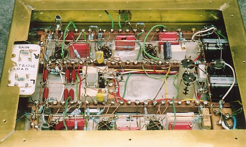
Rocket with standard Wima coupling C.
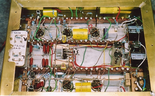
Rocket with Auricap coupling C.
Only the coupling caps in the signal path were changed to
Auricaps.
Bypassing of PSU electro-caps and parts of phono circuit prone
to RF oscillations was done
with polyester caps. I believe such rail bypassing caps have
negligible effect on the great sonic
character of such tube amps. I remain doubtful Auricaps improve
the sound and heard no reason
to change my own amps from red-box Wimas. But the customer was
always king, and when
asked for Auricaps, he got them.
For power supply details see Nemo line preamp and
power supply
Back to index page